Ansys Assistant will be unavailable on the Learning Forum starting January 30. An upgraded version is coming soon. We apologize for any inconvenience and appreciate your patience. Stay tuned for updates.
General Mechanical

General Mechanical

Topics related to Mechanical Enterprise, Motion, Additive Print and more.

Appropiate simple support BCs to compare solid and shell model for sandwich

    • Simon Møller Kristensen
      Subscriber

      Hi

      I am trying to model a sandwich plate using SOLID186 elements in Ansys Mechinal APDL. To validate my results I am comparing to a shell model which is easy to implement (reason I want to use Solid is that I am later gonna create inserts inside the sandwich). 

      The model I am making is a square plate with a weak core and two strong faces. It is simply supported in all edges in the midplane. The pressure is a uniformly distributed pressure in the midplane of the sandwich. 

      Right now the solid model is matching the shell model in deflection and core transverse shear. However the normal stresses in the faces are higher by a factor of 2 compared to the shell model.

      I think my problem might be in simulating the same simple supports for the solid model as I want the sides of the model to rotate around the midplane as they are for the shell model (see picture)

      Shell model - core and face are rotating perfectly around the midplane.

      I have tried all kinds of different approaches using CERIG and MPC184 but none have proven succesfull yet. 

      The closest I have come is by using the CERIG command and MASS21 elements to constrain the node at the midplane (Master) to the nodes away from the midplane (slaves) in order to try constraining the slaves to rotate around the master (see picture).

      However, as you can see from the following results, the upper and lower edges of the sandwich are not rotating around the midplane in the same manner as for the shell model.


      Do any of you know how to implement simple support BCs to a solid model in order to achieve the same behaviour as a simply supported shell model?

      Another point I see as problematic is that the SOLID186 element does not have rotational degrees of freedom, which I guess is the whole problem since you would need to impose the rotational DOF in some other way.

      I have struggled with this problem for weeks know, so all input is highly appreciated.

    • Simon Møller Kristensen
      Subscriber

      Just to make it more clear how I would like the solid model to behave like at the supported edges. 

    • peteroznewman
      Subscriber

      I used Workbench instead of APDL classic interface and reused a previous student’s model to show you this example. I used a Remote Displacement, Behavior=Rigid, with a pilot node at the center of the end face. One one end there are four constraints as shown below. 

      On the opposite end are three constraints, though the rotation about X is optional. 

      These constraints provide the desired deformed shape.

      I hope you can translate these Workbench terms into APDL constraints.

    • Simon Møller Kristensen
      Subscriber

      Thank you for your input Peter

      I have not been able to find the direct translation of the workbench terms into APDL terms.

      Would it be possible for you to send the file you have used for your workbench model, so I can try to use for my own problem?

    • peteroznewman
      Subscriber

      Hello Simon,

      Here is a link to the APDL code in a Sandwich.inp file: https://jmp.sh/D6RpYMU

      Here is a link to the ANSYS 2022 R1 archive file: https://jmp.sh/16sUstc

      In Sandwich.inp, look for the following lines

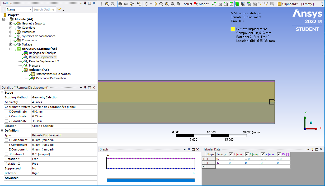
      /com,*********** Create Remote Point “Internal Remote Point” ***********
      ! ——– Remote Point Used by “Remote Displacement” ——–
      *set,tid,6
      *set,cid,5
      et,cid,174
      et,tid,170
      keyo,tid,2,1               ! Don’t fix the pilot node
      keyo,tid,4,0               ! Activate all DOF’s due to large deformation
      keyo,cid,12,5              ! Bonded Contact 
      keyo,cid,4,2               ! Rigid CERIG style load
      keyo,cid,2,2               ! MPC style contact
      eblock,10,,,24
      (15i9)
           2159        5        5        5        0      344      349      801      840
           2160        5        5        5        0      345      344      840      839
           2161        5        5        5        0      346      345      839      838
           2162        5        5        5        0      348      346      838      802
           2163        5        5        5        0      344      341      350      349
           2164        5        5        5        0      345      342      341      344
           2165        5        5        5        0      346      343      342      345
           2166        5        5        5        0      348      347      343      346
           2167        5        5        5        0      341      339      340      350
           2168        5        5        5        0      342      338      339      341
           2169        5        5        5        0      343      337      338      342
           2170        5        5        5        0      347      336      337      343
           2171        5        5        5        0      339      665      672      340
           2172        5        5        5        0      338      666      665      339
           2173        5        5        5        0      337      667      666      338
           2174        5        5        5        0      336      671      667      337
           2175        5        5        5        0      665      668      484      672
           2176        5        5        5        0      666      669      668      665
           2177        5        5        5        0      667      670      669      666
           2178        5        5        5        0      671      482      670      667
           2179        5        5        5        0      670      482      961     1000
           2180        5        5        5        0      669      670     1000      999
           2181        5        5        5        0      668      669      999      998
           2182        5        5        5        0      484      668      998      964
      -1
      *set,_npilot,1121
      _npilot836=_npilot
      type,tid
      mat ,cid
      real,cid
      tshape,pilo
      en,2183,_npilot
      tshape
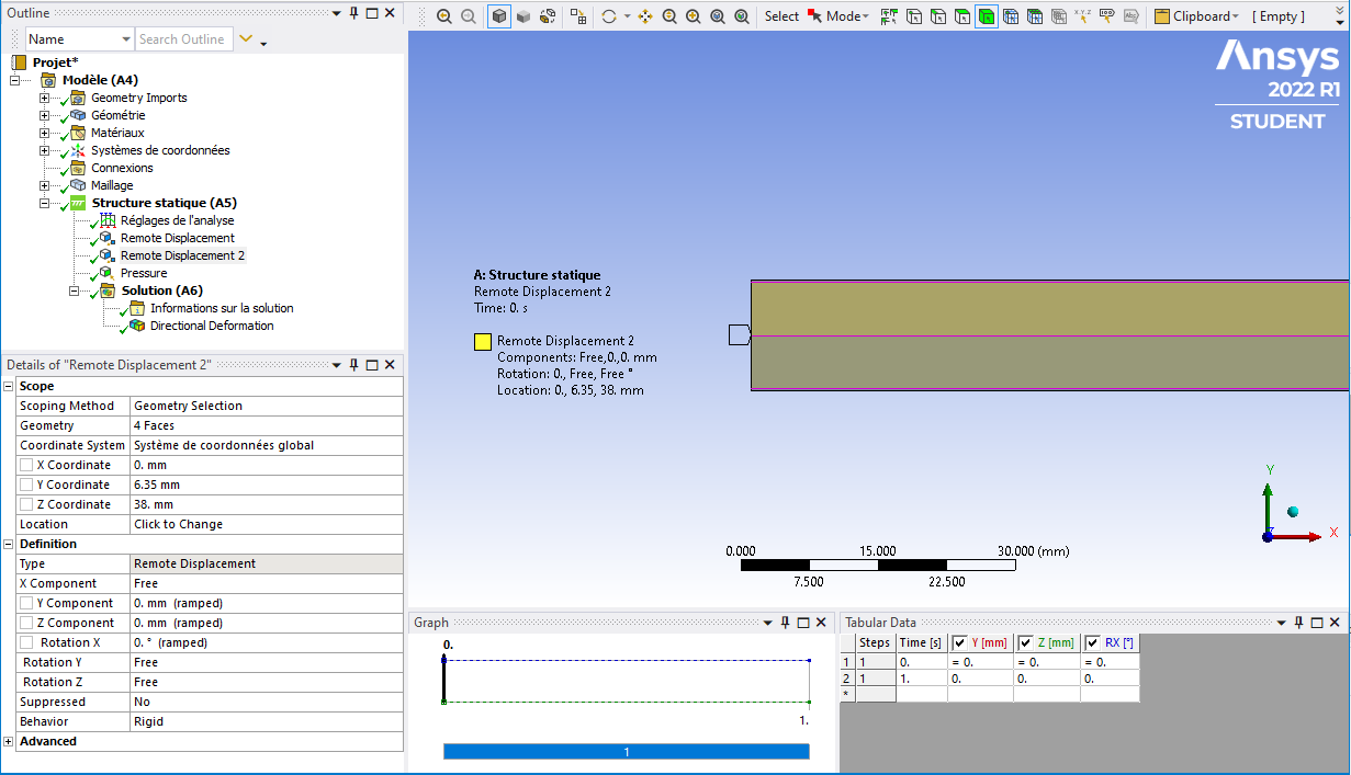
      /com,*********** Create Remote Point “Internal Remote Point 2” ***********
      ! ——– Remote Point Used by “Remote Displacement 2” ——–
      *set,tid,8
      *set,cid,7
      et,cid,174
      et,tid,170
      keyo,tid,2,1               ! Don’t fix the pilot node
      keyo,tid,4,0               ! Activate all DOF’s due to large deformation
      keyo,cid,12,5              ! Bonded Contact 
      keyo,cid,4,2               ! Rigid CERIG style load
      keyo,cid,2,2               ! MPC style contact
      eblock,10,,,24
      (15i9)
           2184        7        7        7        0      412      478      807      803
           2185        7        7        7        0      478      479      806      807
           2186        7        7        7        0      479      480      805      806
           2187        7        7        7        0      480      473      804      805
           2188        7        7        7        0      480      475      474      473
           2189        7        7        7        0      479      476      475      480
           2190        7        7        7        0      478      477      476      479
           2191        7        7        7        0      412      411      477      478
           2192        7        7        7        0      475      273      274      474
           2193        7        7        7        0      476      272      273      475
           2194        7        7        7        0      477      271      272      476
           2195        7        7        7        0      411      335      271      477
           2196        7        7        7        0      273      795      794      274
           2197        7        7        7        0      272      796      795      273
           2198        7        7        7        0      271      797      796      272
           2199        7        7        7        0      335      733      797      271
           2200        7        7        7        0      795      800      481      794
           2201        7        7        7        0      796      799      800      795
           2202        7        7        7        0      797      798      799      796
           2203        7        7        7        0      733      483      798      797
           2204        7        7        7        0      481      800      967      962
           2205        7        7        7        0      800      799      966      967
           2206        7        7        7        0      799      798      965      966
           2207        7        7        7        0      798      483      963      965
      -1
      *set,_npilot,1122
      _npilot839=_npilot
      type,tid
      mat ,cid
      real,cid
      tshape,pilo
      en,2208,_npilot
      tshape

      Down in the Solution part of the input file is where the displacements are applied to those two pilot nodes:

      d,1121,ux,0.
      d,1121,uy,0.
      d,1121,uz,0.
      d,1121,rotx,0.
      d,1122,uy,0.
      d,1122,uz,0.
      d,1122,rotx,0.

      Good Luck!

Viewing 4 reply threads
  • The topic ‘Appropiate simple support BCs to compare solid and shell model for sandwich’ is closed to new replies.
[bingo_chatbox]