Ansys Assistant will be unavailable on the Learning Forum starting January 30. An upgraded version is coming soon. We apologize for any inconvenience and appreciate your patience. Stay tuned for updates.
General Mechanical

General Mechanical

Topics related to Mechanical Enterprise, Motion, Additive Print and more.

Ansys Workbench边界条件图例问题

    • 1512514147
      Subscriber

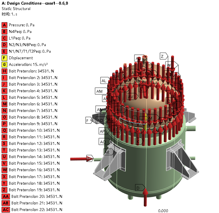
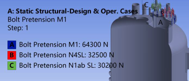
      在边界条件螺栓预紧力显示界面,怎么能做到第二张图中的效果,我的(图1)会把所有螺栓预紧力单独显示,但是我看别人的可以合并,如图2,请问是施加方式的问题还是显示设置的问题?我是使用对象生成器批量生成的

    • Ankush Choudhary
      Ansys Employee

      Hi,

      It seems in the first image separate bolt pretension objects are applied on the bolts. In the second image, multiple bolts are selected under a single bolt prestension object. Then the Random option has been used under Display to have different colors for the pretension objects.

      • 1512514147
        Subscriber

        First of all, thank you for your reply.

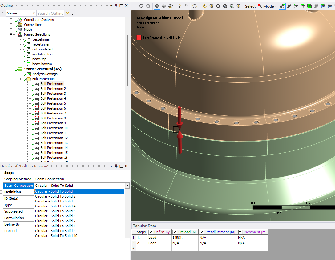
        I use beam elements instead of bolts, when the "Scoping Method" is "Beam Connection", I can't select multiple bolts under a single bolt prestension object; they can only be applied one by one.(As shown in Figure 1)

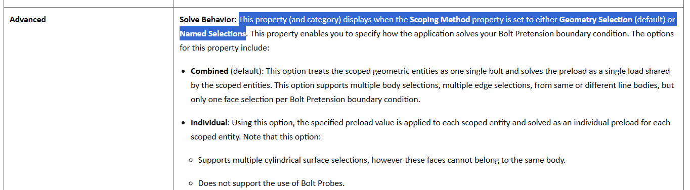
        When the "Scoping Method" is "Geometry Selection", the same problem occurs: it can only be selected one-to-one.

        May I ask how I can achieve what you mentioned: "multiple bolts are selected under a single bolt prestension object".

        THANKS!!!
    • Deepak
      Ansys Employee

      In Ansys Mechanical, the ability to group multiple bolts under a single bolt pretension object depends on the type of elements and the scoping method used. For solid bolt geometry, you can select multiple bodies or faces and apply a single bolt pretension object. However, the software only allows you to assign one Beam Connection per Bolt Pretension object; multiple beam bolts cannot be grouped under a single pretension object using the "Beam Connection" scoping method.

      • 1512514147
        Subscriber

        Thank you for your reply, it feels like the problem is already half solved.
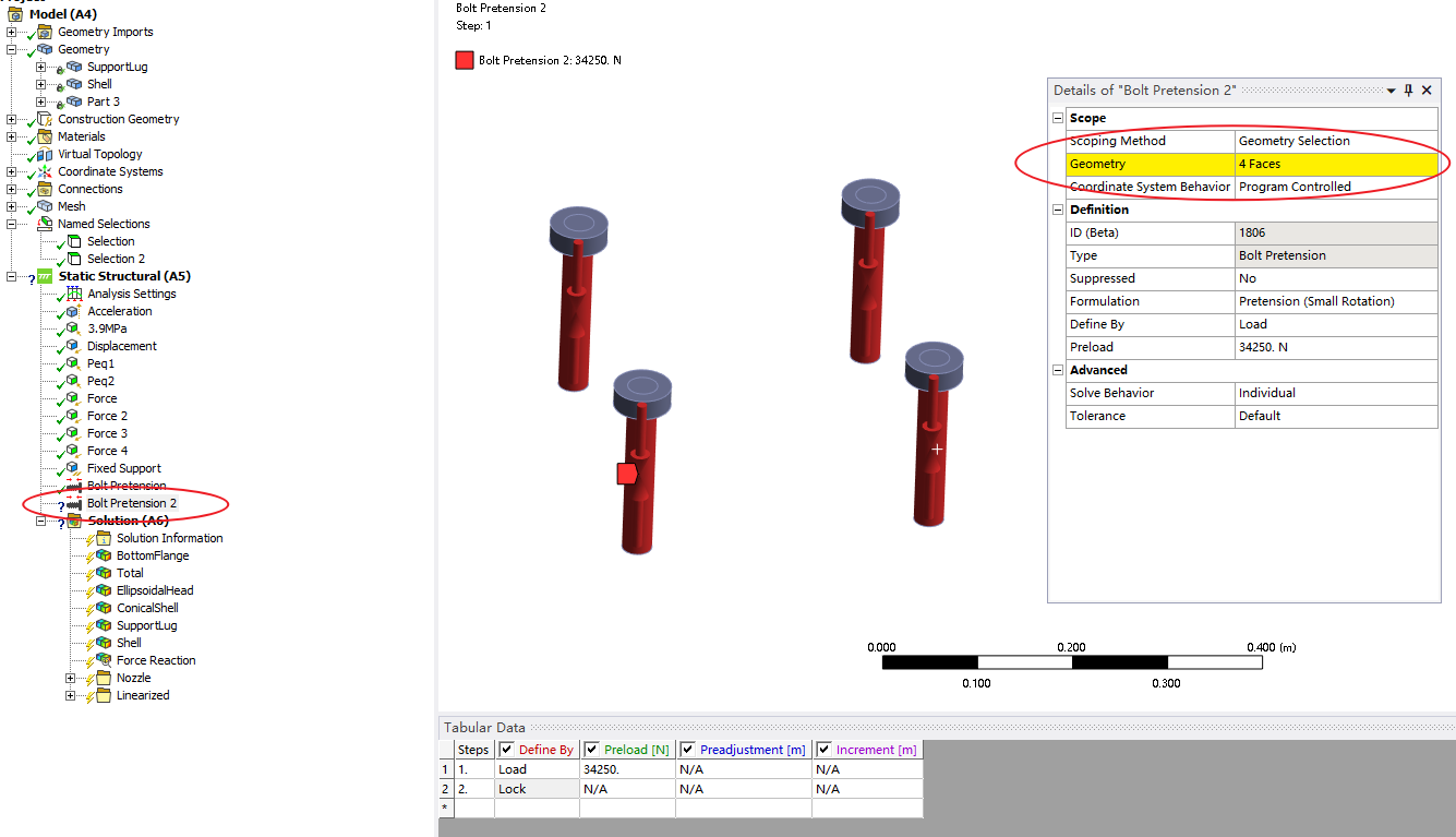
        But when I select the four faces as the bolt preload application surface, it shows up yellow

        • 1512514147
          Subscriber

          I understand. Now I have created a coordinate system that can represent the axial directions of these four bolts and changed the selection from face to body, and the problem is solved.

Viewing 2 reply threads
  • You must be logged in to reply to this topic.
[bingo_chatbox]