TAGGED: error-modal-frequency
-
-
November 10, 2021 at 8:07 pm
lbtung248
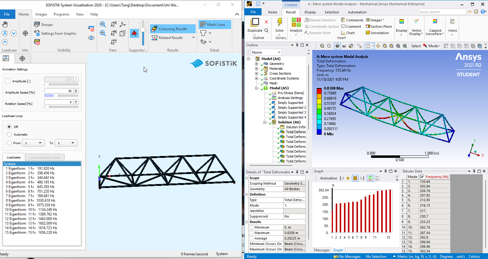
SubscriberHi everyone, i have been working on a space truss model (Mero space truss system) and tried to perform modal analysis. However the first frequency also the whole frequency range from Ansys doesn't match with my other FE software models (Sofistik and SAP2000): While in sofistik my first frequency is 191.82 Hz and for the first 15 modes it ranges up to 1656 Hz, in Ansys my first frequency is only 155.64 Hz and only ranges up to 302Hz for the first 15 modes.
I tried to cross checked the two models from the material with correct module of elastic, also the cross sections, dimensions, etc, structural self-weight, support reactions, ... All of these are the same however the modal analysis gave me a different results as mentioned. I checked with every single mode and found out that in my Ansys model there is only local modes and when i changed the boundary condition from simply supported to fixed, the frequency range in Ansys doesn't change too much. This make me think that my beam elements have no sufficient stiffness. I don't know this assumption is correct or not and I can't find a way to fix my model.
Can anyone give me some hints where is my problem?
(I can upload my models if needed)
November 10, 2021 at 9:17 pmhesamkeshavarzz
Subscriber
Its because the difference between the modeling of the connections between the trusses in the two softwares. although ANSYS has more capability to model a wide range of connections, I think the civil eng softwares like SAP and ETABS has a better equations to medel the connection in the structures.
November 11, 2021 at 10:16 amSubscriberThank you ! What i did in Ansys was: in the geometry SC, in Workbench tab, i pressed share the joints.
So from what i understand now is that this is the default connection type between truss member and the definition of these connections is different from other FE software. Con you explain a bit more about wide range of connections in Ansys? How can I adjust the fixity of these connections so that it could match the result in other FE software?
November 11, 2021 at 5:08 pmSubscriberIts beyond the scope of our chat. I think you should study more about the theory of your civil engineering software, and know how it form the stiffness matrix, then, simulate the connections with details in ansys,
good luck
November 11, 2021 at 5:36 pmSubscriberThank you!
November 11, 2021 at 6:54 pmErKo
Ansys EmployeeHI @lbtung248
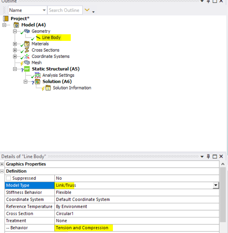
You are using truss elements in SOfistik, but beam elements in Ansys -
So mesh with only one element per structural member (so set you element size to 10 m or something very large to get one element per member), and the choose link/truss type (which is a truss element) under the line body definition and model type details/
See here on how to do that:
 All the best
Erik
November 12, 2021 at 8:34 amAnsys EmployeeGood Morning - not sure you saw the previous post, but if you do the below change then you should get very similar results I believe (assuming you have the same material properties, dimensions, cross sections, boundary conditions, in Sofistik and Ansys):
HI @lbtung248
You are using truss elements in SOfistik, but beam elements in Ansys -
So mesh with only one element per structural member (so set you element size to 10 m or something very large to get one element per member), and the choose link/truss type (which is a truss element) under the line body definition and model type details/
See here on how to do that (set it to link/truss instead of beam):
All the best
Erik
November 15, 2021 at 10:47 amSubscriberThank you very much for the help! It worked!
Viewing 7 reply threads- The topic ‘Ansys Modal analysis’ is closed to new replies.
Innovation Space Trending discussions
 Top Contributors
-
peteroznewman
 6450
6450 -
scabo
 1906
1906 -
Dennis Chen
 1457
1457 -
javat33489
 1308
1308 -
Shyam Prasad V Atri
1022
Top Rated Tags
© 2026 Copyright ANSYS, Inc. All rights reserved.
Ansys does not support the usage of unauthorized Ansys software. Please visit www.ansys.com to obtain an official distribution.
-