-
-
May 16, 2024 at 8:30 am
rosar
SubscriberHi!
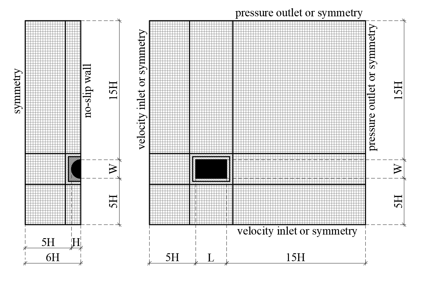
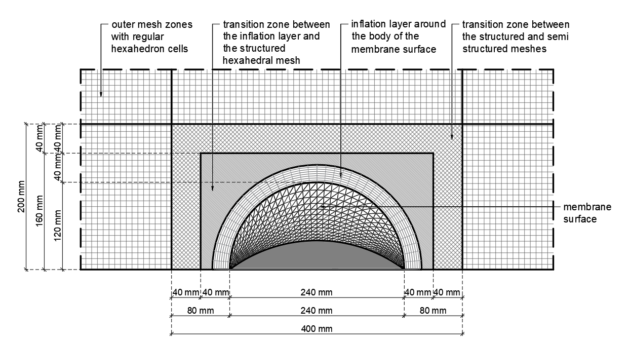
I am new to Ansys Fluent and have a technical question. I want to carry out a wind engineering analysis of a structure. I have previous results of wind tunnel tests for multiple wind directions. I want to analyze the same wind directions numerically in Ansys. The current method I applied is that I set the boundary conditions in every new wind direction by changing the direction of the velocity vectors in the boundary inlets. I used a structured mesh where I use hexahedral elements in the outer domain parallel to the x-y axes, and an inner domain where I make a transition between the structutred mesh and th inflation layer around the surface.
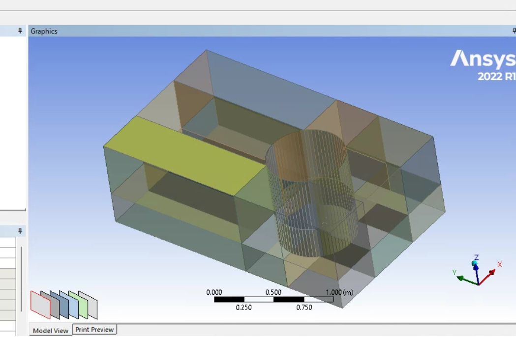
I know that I can apply an alternative method by keeping the same boundary conditions and rotating the structure inside the flow domain (I think this is called an O-grid, but I'm not sure). How can I do this? My structure is a 3D tensile membrane, so the geometry is complex in terms of its doubly curved surface. I generated the geometry of the membrane surface in a CAD software, and imported that into desgin modeler. Then I do the enclosure and everything else in Ansys. I want to keep the structured mesh that I introduced in the previous section.
Do you have any advice or recommendations? Which method is better? The rotating method would spare me some computational capacity since the flow domain can be smaller. But I found somewhere that the interface can cause inaccuracies compared to the fix mesh.
I only found example problems online (images, descriptions, videos) about 2D problems where they rotated the object.
Sorry for the long question. I attach photos about the current set up of the mesh.

-
May 16, 2024 at 8:42 am
rosar
SubscriberHi! I have an additional comment. I tried to generate the whole flow domain in the CAD software (Rhino3d and Grasshopper), because this way i can totally parametrize the definition. I wanted to import that geometry into fluent, and do the meshing there. (Basically I wanted to skip using design modeler). But when i imported the geometry and checked it in design modeler, everything was imported as a shell, and not solid elements. -
May 16, 2024 at 8:43 am
-
May 16, 2024 at 12:37 pm
Rob
Forum ModeratorCheck the import options in DM, I think it defaults to surfaces for some formats. The sliding mesh approach is sensible, but I've found it better to rotate the outer region so when post processing you keep the "building" orientation constant.
One comment, carefully check your definitions for map/grid north, true north, magnetic north and similarly for the wind rose. You'd be surprised how many variations you'll find.....
-
- The topic ‘Ansys fluent rotate boundary/change wind direction’ is closed to new replies.


-
3432
-
1057
-
1051
-
896
-
892

© 2025 Copyright ANSYS, Inc. All rights reserved.


