Hello Matthew,
Your analysis is right. If the path is fully within one single body, DPF (or APDL) results and Mechanical Path result will match.
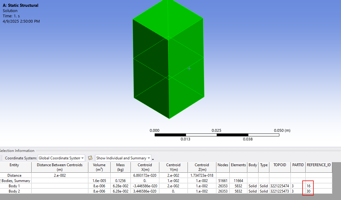
However, if the Path is defined on an edge (for example) which is shared between two bodies, the Path results are considered from the nodes of one of the body, which has higher geometry ID (internal ID which can be displayed when selecting a geometry and clicking on Selection Information) as shown below. The example here shows that I selected two bodies and I can see from the selection information that the IDs are 16 and 30. Hence, if a path is scoping one of the edges shared between these two blocks, the results are taken from Body with id 30. However, DPF or APDL will get averaged result. You can verify this by scoping only the body with highest id when scripting with DPF to match the results between DPF and Mechanical.
This has also been documented in help as shown below.
https://ansyshelp.ansys.com/account/secured?returnurl=/Views/Secured/corp/v231/en/wb_sim/ds_path_results.html
If a Path traverses multiple surface or solid bodies and if a Path point lies on the interface between the distinct bodies, the application only displays the body used to create the result. For example, as illustrated here, a Path is defined by the edge between two surface bodies. Note that both bodies are scoped. However, the result contours on the Path are only based on body A.
In the first two images, a body (A and B) is specified in the Geometry property for the result. Only one body is displayed in the Geometry window. And, note that the stresses for Body A and Body B differ. In the third image, the result is scoped to both bodies. The stresses displayed for this third image match those of Body A because it has the highest identifier and therefore selected by the application by default.
Hope this helps.
Best regards,
Rohith