TAGGED: aqwa, assembly, connection, hydrodynamic-diffraction, joint
-
-
January 26, 2022 at 3:27 pm
burning08
SubscriberJanuary 27, 2022 at 2:57 pmJanuary 28, 2022 at 11:22 amburning08
SubscriberHello ybi Thank you for your response. I have defined 8 fenders as you proposed before (I'm not sure about the type and action). I get this error when I press solve on hydrodynamic response.
Best Regards.
January 28, 2022 at 12:03 pmYu Bi
Ansys EmployeeHi, as the error suggests, if a structure is marked as fixed, you need to define an additional rigid joint to fix it to a fixed point first.
January 28, 2022 at 3:06 pmburning08
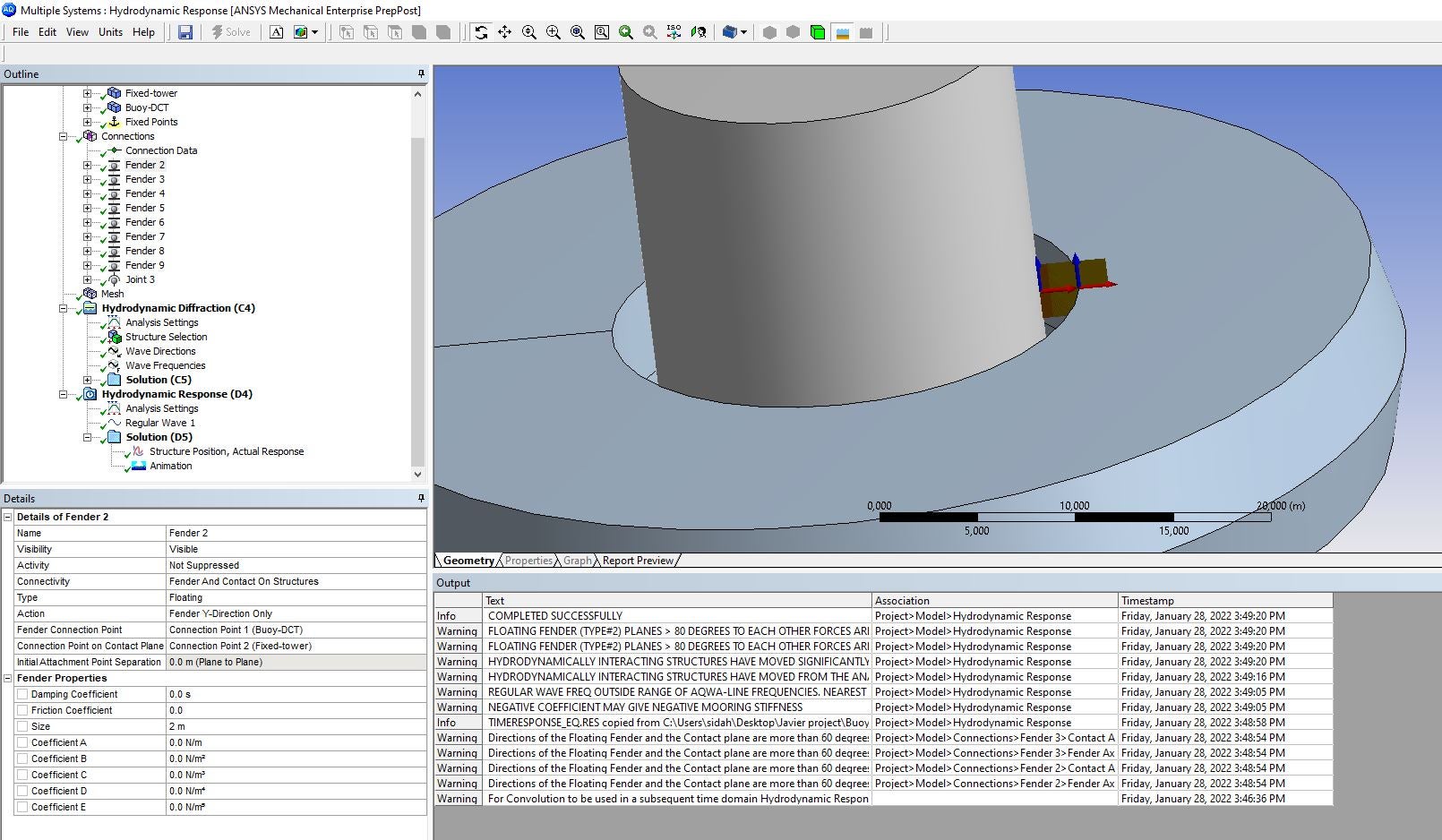
SubscriberHi ybi, Thank you very much, I have defined a rigid joint on the bottom of the fixed tower and the hydrodynamic response solver run normally. However, the buoy seems to react with the wave until it hit the tower the continues acting with the waves frequencies. It seems that the fenders which I defined are not set properly. Please check the attached video and image, could you explain how to set fenders?
My concern is to get only the vertically movement next to the fixed tower.

Best Regards
January 28, 2022 at 3:37 pmYu Bi
Ansys EmployeeYou need to set the stiffness coefficient for the fender, and if you don't want the fender is compressed at the beginning, please give an initial distance (larger or equal to the fender size) between two connection points of the fender.
February 3, 2022 at 3:51 pmburning08
SubscriberHello ybi I have tried different configuration, different fenders, properties... but I got always the same results. the buoy seems to react as a ship with the waves, also the structures are interacting to each other, as the fenders which were compressed had no meaning! Anyway, I don't know exactly what to do ? I thought it was a simple problem: all I need is just a vertically motion of the Buoy across the tower... Theoretically it seems so simple but I'm still struggling to realize it. I can share the simulation file, if you wanna try on it or you can take some time and show me how to set up the simulation properly. I will appreciate your help. Please check the attached animation and images, just to get an idea of my problem.
Best regards
February 3, 2022 at 4:38 pmYu Bi
Ansys EmployeeHow much is the wave force/moment in the x-direction and about y axis? From what I saw, the fender is still a bit soft. You can output the fender force and other wave forces to see if the fender is stiff enough to counter-balance the wave force.
February 3, 2022 at 5:25 pmburning08
SubscriberThose are the results attached. I chose the fender which is faced to the coming wave from X direction.
February 4, 2022 at 2:23 pmYu Bi
Ansys EmployeeSorry, I think it is because the direction of the fender's contact axes is not correct. The action axis of the contact axes should point to the fender in order to let the fender work. The action axis in your picture is the x-axis. So, now I don't know if the stiffness coefficient value set in the picture is good or not, but as I mentioned you can compare the fender force with the wave forces to have a check. If the fender stiffness is too big, it will require a very small time step. The wave forces I mean are mainly the F-K force, diffraction and radiation forces.
February 4, 2022 at 4:38 pmburning08
SubscriberHello ybi,
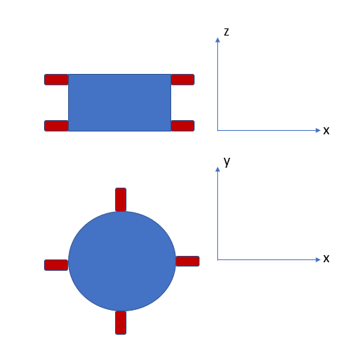
Thank you very much for your suggestions. So, I changed the fenders action to omni directions, I choosed this time only 4 fenders on the X axis top and botom of the buoy contact with tower. Now on the graph that fender force is clearly observable. It seems that fenders are doing their job; however, is it possible to set only the vertical movement (movement of the buoy only Z direction). Please, chech the graph and animation, let me know your suggestions.
Best regards
February 4, 2022 at 5:34 pmYu Bi
Ansys EmployeeYou can increase the distance on the z-axis direction between the two fenders on one side. This will increase the moment the two fenders can provide, which will restain the rotation more efficiently.
February 4, 2022 at 11:56 pmburning08
SubscriberHello ybi I tried 10 fenders this time ( 5 each side, equally spaced, same properties). After many manipulations on the damping coefficient and reducing time step, while verifying the distance after each solution between 2 points (one on the buoy and one fixed on tower). I succeed let's say 95% to force the buoy going on vertical motion (check the animation video).
Thank you very much again for your help, couldn't do this without your suggestions.
You're the best Best regards.
April 28, 2022 at 12:10 pmGreyFibre
SubscriberDear ybi, I come across the same problem, but I have no idea how to set the stiffer coefficent. i canÔÇÿt find any entrance.I'm a new learner. Best regards.
May 16, 2022 at 9:25 amYu Bi
Ansys EmployeeHi, GreyFibre Sorry for the late reply. In the detail panel of the fender, you can see Coefficient A, Coefficient B, .... Those are the stiffness coefficients, and they are the coefficients of the polynomial function, which is used to calculate the total stiffness. See Aqwa Theory manual Fender section.
Viewing 14 reply threads- The topic ‘Ansys Aqwa, how to set only a vertical movement?’ is closed to new replies.
Ansys Innovation SpaceTrending discussionsTop Contributors-
2979
-
970
-
857
-
750
-
599
Top Rated Tags© 2025 Copyright ANSYS, Inc. All rights reserved.
Ansys does not support the usage of unauthorized Ansys software. Please visit www.ansys.com to obtain an official distribution.
-
The Ansys Learning Forum is a public forum. You are prohibited from providing (i) information that is confidential to You, your employer, or any third party, (ii) Personal Data or individually identifiable health information, (iii) any information that is U.S. Government Classified, Controlled Unclassified Information, International Traffic in Arms Regulators (ITAR) or Export Administration Regulators (EAR) controlled or otherwise have been determined by the United States Government or by a foreign government to require protection against unauthorized disclosure for reasons of national security, or (iv) topics or information restricted by the People's Republic of China data protection and privacy laws.


