-
-
April 8, 2024 at 7:03 am
Kimmo Haanpää
SubscriberHei,
I am trying to assess and gain a general understanding of the modeling capability. I have created a toy model with two straight conductors, the magnetic field force of which I can theoretically calculate. I use this theoretical value as a goodness metric for the value provided by the model. Below is an image of the model along with descriptions of the parameters.
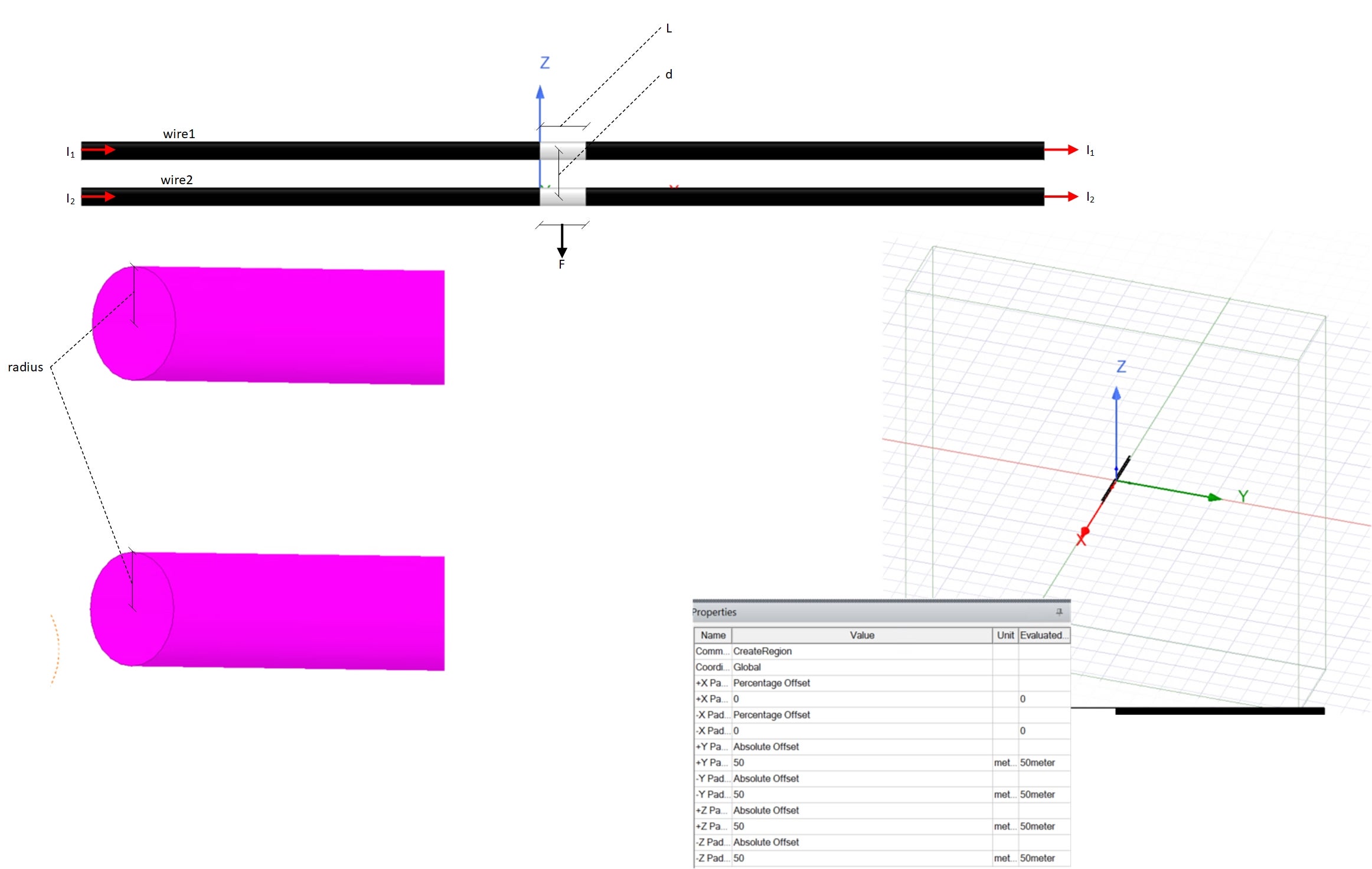
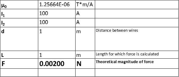
The formula for the theoretical value of force.
The model parameter values are provided below.
The simulated force results are provided for six different conductor cross-sections (0.001, 0.01, 0.1, 0.2, 0.3, and 0.4).
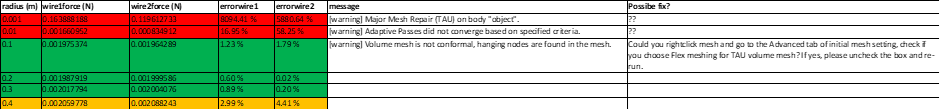
I believe that the cases with 0.001 and 0.01 are not pathological, and I wonder why the program fails to calculate correctly in those instances (assuming that the green cases are calculated correctly). I am trying to gain an overall understanding of the software’s capabilities and how I can address the situation when error messages occur.
Is it possible to configure the modeling software so that the cases with 0.001 and 0.01 come sufficiently close to the theoretical result (the correct result)? -
April 11, 2024 at 1:39 pm
Ivonne Marti Dura
Ansys EmployeeHi Kimmo,
In your last image, in concrete in the image column. I can see that you have warnings for the 0.001 and 0.01.
Warning: Major Mesh Repair -> Here you can try to use mesh operations to improve the mesh and/or try to test using the Classic mesh
Warning: Adaptive passes did not converge -> This is a clear message. You need to increase the number of passes. If the simulation does not converge then it is normal you are not getting accurate results. Please be sure your simulations converge.
I hope this helps.
Ivonne
-
April 22, 2024 at 10:21 am
Kimmo Haanpää
SubscriberThank you for your response.
I recommend that you create tutorial videos addressing various warnings and error notifications, along with their potential fixes.
-
- The topic ‘Analysis of Modeling Capabilities’ is closed to new replies.
- Ansys Maxwell 3D – eddy current
- Maxwell circuit – PWM
- Plotting Ex, Ey and Ez in vector forms individually
- Simplorer+Maxwell Cosimulation results and Maxwell results mismatch
- Ansys-MATLAB Co-Simulation
- Compute near field simulation with current
- Y wiring method and the start and end points of winding.
- Calculating E-field tangential to a 2D resonant structure on a sapphire chip
- Ansys Resonance simulatioin error
- How does Ansys Twin Builder implement different simulation steps for subcircuits
-
2262
-
925
-
599
-
591
-
497
© 2025 Copyright ANSYS, Inc. All rights reserved.