Electronics

Electronics

Topics related to HFSS, Maxwell, SIwave, Icepak, Electronics Enterprise and more.

AlNiCo hysteresis simulation

    • pavel.kirienko
      Subscriber

      I know this question has been asked many times, but sadly none of the previous discussions I encountered appear to contain a definitive answer on how to make this work.

      I have a very basic Maxwell 3D transient simulation setup with a cylindrical magnet and a coil wound around it. I apply a current pulse through the coil, which causes a strong magnetic field to be induced inside the magnet for a few microseconds. The field is sufficiently strong to reverse the magnetization of the cylinder. After the current is removed, I expect the cylinder to reverse its magnetization; however, it just returns to its original state. The behavior of this simple simulation setup does not match the behavior of an actual prototype I assembled on the bench; the reason the prototype was built is to validate the correctness of Maxwell predictions but right now it is failing that.

      The cylinder is made of LNG37 and the same material is selected in the simulation, taken from the RMxpert library; the material definition includes the correct BH curve spanning the first two quadrants, which should be sufficient to simulate the hysteresis effect according to what I read in the help and here on the forum.

      Below are the plots of the solenoid current over time and the magnetic flux magnitude; the magnitude starts from 50 mT and goes back to that as expected, but what is unexpected is that the original magnetization direction is restored.

      Can you please share any pointers what is it that I am doing wrong? Thanks!

    • GLUO
      Ansys Employee

      Hello,

      Did you turn on demagnetization calculation?

      Setup Demagnetization Calculation
      – In the Project Manager window, RMB on Excitation → Set Magnetization Computation…
      – In the Set Demagnetization/Magnetization Computation window, check Compute demagnetized 
      operating points and Press OK.

      GL

    • pavel.kirienko
      Subscriber

      Yes, I tried that. That setting has no effect on my simulation. My understanding, after extensive RTFM, is that I need to set up a chain of three designs to model the magnetic hysteresis effects, as described in the docs. I'm wondering if it's possible to somehow do it in a single design; can you share any advice?

      I also understood that I need to define the BH curves via the core loss model instead of the magnetic permeability model if I want to compute magnetization in both directions, right? Sadly the common AlNiCo grades provided in the materials library don't have the core loss model defined so I will need to supply my own material data, which is a bit inconvenient.

    • GLUO
      Ansys Employee

      Hi,

      1. I'm wondering if it's possible to somehow do it in a single design; can you share any advice?

      Yes. It is quite common to simulate magnet demag operating point under over current condition in a single transient design. There is a dedicated section of this topic on ANSYS learning Hub >> Electronics>>Advanced Motor Training>>Workshop 07.

      2.  I need to define the BH curves via the core loss model instead of the magnetic permeability model if I want to compute magnetization in both directions, right? 

      No. A normal BH curve with its knee point is sufficient.

      Is your Mag_B plot on a reference point in the magnet?

      GL


    • pavel.kirienko
      Subscriber

      >There is a dedicated section of this topic on ANSYS learning Hub >> Electronics>>Advanced Motor Training>>Workshop 07.

      I tried accessing the learning hub but I got HTTP error 500. I already contacted the support regarding that; meanwhile, could you please outline the general steps so that I could try them now? Thanks!

      >Is your Mag_B plot on a reference point in the magnet?

      Yes, this is the field magnitude in the center of the magnet, which is a 10x10 mm cylinder.

    • pavel.kirienko
      Subscriber

      I think I found at least part of the problem: I had job parallelization enabled for the transient solver in the HPC options. This caused the time decomposition method (TDM) to be chosen for the problem. The TDM is unable to simulate hysteresis effects directly, as mentioned in the docs at Maxwell Help > Specifying Solution Settings > Setting Analysis Parameters for Transient Solutions > Time Decomposition Method for Maxwell Transient Designs:

      Strictly speaking, TDM cannot support hysteresis modeling. But for soft hysteresis materials, especially for lamination core loss computation, the hysteresis loop, or the coercivity Hc, is very small. [NB: it is not small for AlNiCo]

      This is quite dangerous as the simulation completes successfully without any kind of warning that the results are invalid. I disabled TDM and got much better results. They don’t quite match what I got with the bench prototype yet, though.

      I ran two simulations:

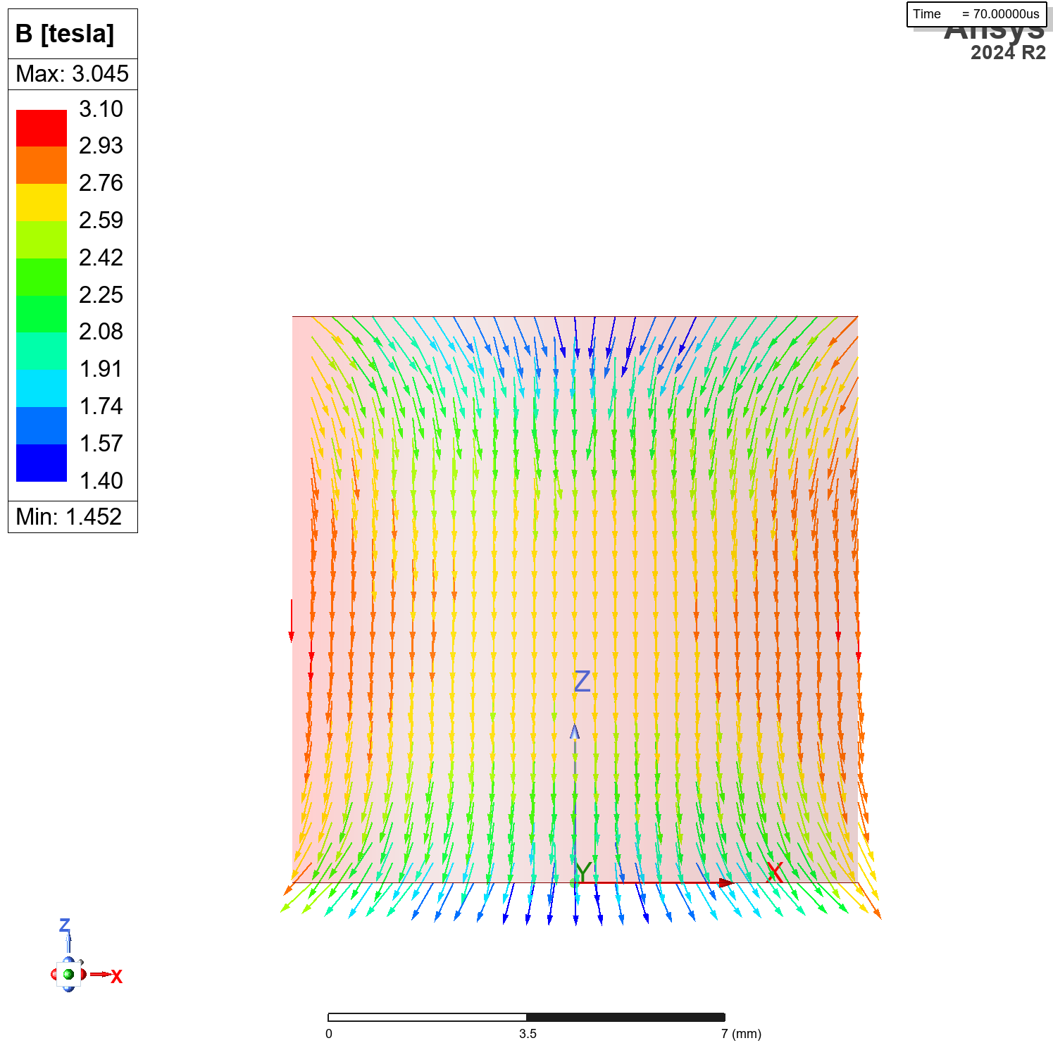
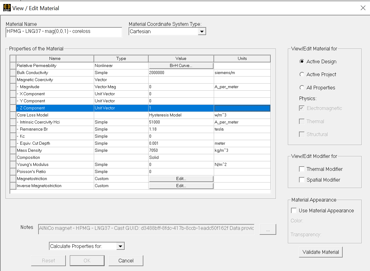
      1. With the BH curve provided with the LNG37 alloy from the standard material library replaced with a core loss model as explained in Maxwell Help > Assigning Boundaries and Excitations for 3D Designs > Setting Demagnetization/Magnetization Computations for Source Designs > Using the Hysteresis Model-Based Magnetization Approach.
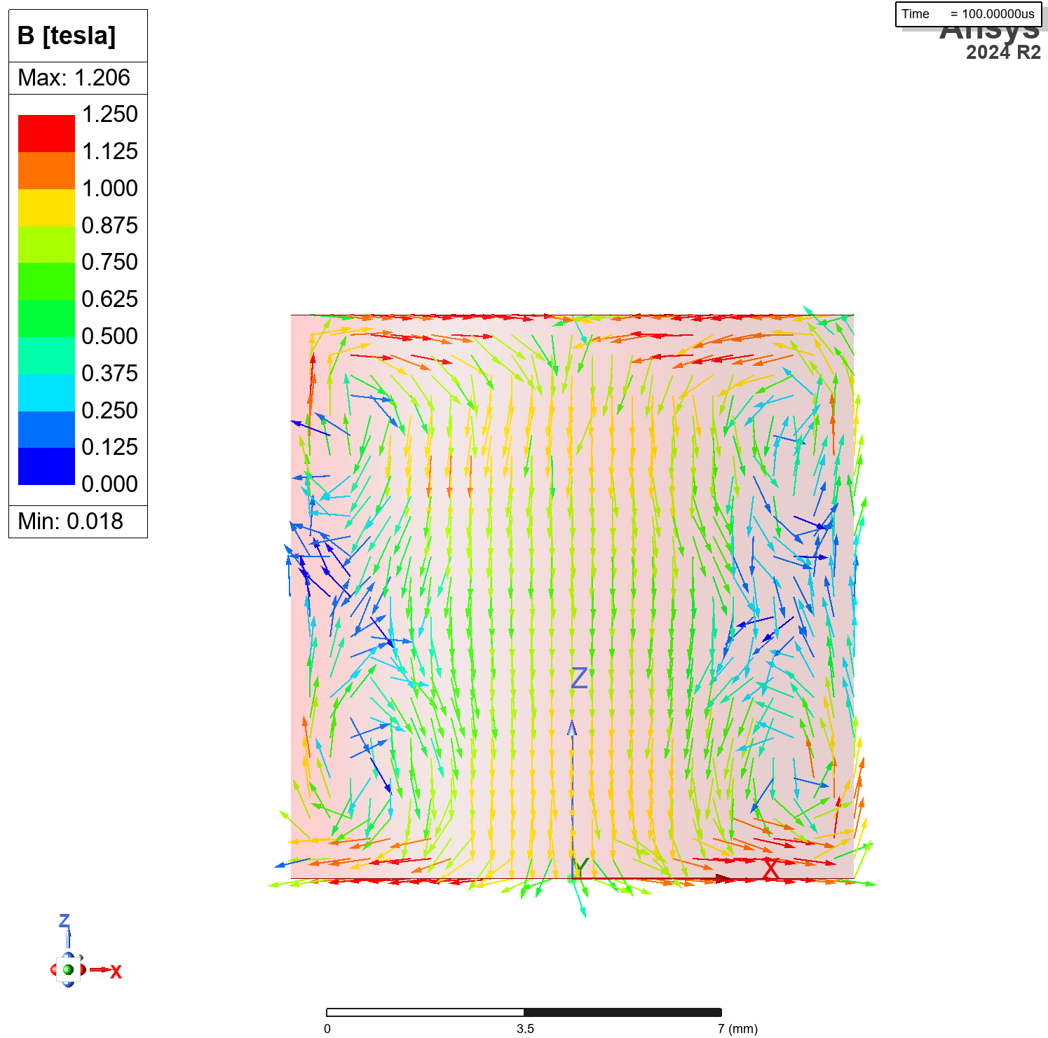
      2. With the original LNG37 material definition.

      The first one resulted in a much better result that approximates what I get with the bench prototype. The second one resulted in the sample being demagnetized — the B vector field is oriented randomly inside the cylinder after the current pulse is removed, and the magnitude is about zero.

      Could you please confirm that this:

      A normal BH curve with its knee point is sufficient.

      is sufficient to compute both demagnetization and magnetization of the body? That does not seem to be the case or I'm doing something wrong.

    • pavel.kirienko
      Subscriber

      Here is the additional information on what I get in the first case, where I replace the BH curve of the LNG37 material from the standard library with the core loss model. The magnetization at the end of the current pulse and then at the end of the simulation (some time after the pulse is completed) is shown below.

      While in this case I can successfully simulate magnetization, the core loss model has two limitations that are fatal in my case:

      • It does not seem to be possible to define the initial magnetization, or I don't understand yet how to do that. A screenshot of the material configuration is shown below; I expect it to be magnetized along the Z axis, but it only works with the original BH curve, not the core loss model.

      • The magnetization results in flux closures (loops), as seen on the second image above. I understand this is caused by the fact that the core loss model does not support anisotropy at all. From the docs:

      magnetization is always considered as isotropic magnetization, that is, magnetization direction is determined by the orientation of the computed field

      Unless there is a way to address these two limitations, I should be using the regular BH curve, but then I need to understand how to simulate both demagnetization and magnetization.

    • pavel.kirienko
      Subscriber

      I have another question related to anisotropy. I change the permeability to anisotropic, then, just for the sake of validation, I supply the original BH curve for all three magnetization directions. The solver fails with an error "One of the input ascending/descending curves does not valid for hyeteresis loop" (sic). At the same time, the solver has no problem accepting the same curve for isotropic materials.

      I've looked at the Maxwell help about anisotropic materials but I don't seem to find an explanation why would the solver accept the same BH curve for isotropic materials but reject it for anisotropic ones. Can you please advise?

    • pavel.kirienko
      Subscriber

      Okay, perhaps it's better to go back to the beginning and restate the problem again: Is it possible to simulate an anisotropic magnet that traverses the BH curve from one end to the other?

      Conditions:

      1. We have an anisotropic magnet that is initially magnetized in one direction.
      2. We apply an external field. The magnet responds by changing its magnetization accordingly.
      3. We remove the external field. The magnet returns to some Br in the opposite direction.

      So far I only understand how to simulate that for isotropic magnets. Thanks for any help!

      • GLUO
        Ansys Employee

        Hi,

        Are you using 2024R2 version of AEDT? In 24R2, a new feature was introduced for anisotropic magnet like AlNiCo. New version of Maxwell UI

        1. allows users to specify recoil-line relative permeability for each hysteresis curve and  

        1. allows user to specify the initial magnetization direction for PMs.

        GL

Viewing 8 reply threads
  • You must be logged in to reply to this topic.