-
-
October 12, 2023 at 4:58 pm
yipxx043
SubscriberHello all,
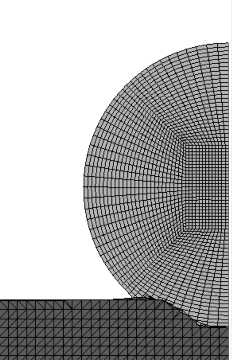
I have attempted to model a brittle ceramic, spherical projectile striking a metallic target. I first started using S-ALE, but it looks like the *MAT_JOHNSON_HOLMQUIST_CERAMICS is not supported in S-ALE (at least in my version of LS-DYNA). So I decided to try a coupled simulation where the brittle ceramic projectile is modeled as the Lagrangian part (ELFORM=1) and the target and void are ALE (ELFORM=11). The target is modeled with MAT_JOHNSON_COOK. I have included some snippets of my solution. I have a lot of questions so I apologize in advance for the length of this post.
- There is clear mesh biasing happening as the erosion critieria is eroding along ~45 degree direction. I modeled the sphere in PrePost using the autometic mesh generation tool to get a solid sphere. Is there any recommendation on how to model a sphere to not have such biasing?
- To add to more of the confusion, it also seems that there are a lot of things to consider in the *CONSTRAINED_LAGRANGE_IN_SOLID card that affected the erosion. The greatest sensitivity I saw was changing FRCMIN from its default of 0.5 to 0.3 (recommended by Jim Day's FSI Modeling PDF) or even lower to 0.1. How do I know what I should be using?
- To add to more of the confusion, it also seems that there are a lot of things to consider in the *CONSTRAINED_LAGRANGE_IN_SOLID card that affected the erosion. The greatest sensitivity I saw was changing FRCMIN from its default of 0.5 to 0.3 (recommended by Jim Day's FSI Modeling PDF) or even lower to 0.1. How do I know what I should be using?
- In the JH2 model for the ceramic projectile, why do I need to have a plastic strain to fracture (FS) value? I thought that that the FS parameter is computed at each time step and would use the computed value to determine damage and then that damage would determine when the element is removed from the calculation? (ref: apps.dtic.mil/sti/pdfs/ADA402374.pdf)
Please see the snapshots at t = 1, 2, 5, and 15 ns below.
Thank you,
Peter
- There is clear mesh biasing happening as the erosion critieria is eroding along ~45 degree direction. I modeled the sphere in PrePost using the autometic mesh generation tool to get a solid sphere. Is there any recommendation on how to model a sphere to not have such biasing?
-
October 12, 2023 at 5:02 pm
yipxx043
SubscriberAnother question:
3. How would I go about the mesh refining process to get a grid converged solution? I thought that I would first run the simulations with refining the particle until the solution is unchanging and then refine the target until the solution is unchanging, but I have read in many resources that it is recommended to keep the elements that are coupled (or in contact) to have relativley the same element size? Should I just do the original sequence of grid convergence stated above or is another method recommended to insure grid dependence is removed?
Thanks,
Peter
-
- The topic ‘ALE/FEM Coupled Simulation – High Speed Impact Questions’ is closed to new replies.


-
4989
-
1670
-
1386
-
1243
-
1021

© 2026 Copyright ANSYS, Inc. All rights reserved.


