-
-
May 18, 2023 at 4:06 pm
ricardo.pferreira
SubscriberHi all,
I'm trying to simulate the flow exhaust behavior of GE90-115b during the take-off of a B777-300ER. However, I'm facing several problems when defining the Boundary Conditions at the Inlet/Outlet of the engines. Anyone knows what would be the most suitable BCs definition for this kind of case?
The methods used are:
- Density Based Solver (DBNS) with 2nd order for all equations
- Compressible flow
Input parameters:
Material: Air
Density: ideal-gas
Viscosity: Sutherland
Model: Realizable k-epsilon (2 equ.) w/ Scalable Wall Functions
Operating Pressure: 101325 Pa
Boundary conditions:
Engine Inlet: Mass Flow Inlet (1713.9 kg/s), Pabs (69562 Pa), Tabs: 259K
Engine Outlet: Pressure Outlet at both Core and Bypass outlets (Core: 857K, 107096 Pabs; Bypass: 295K, 101325 Pa)
Solution method: Roe-FDS - Least square - 2nd order
Initialization method: Hybrid
Any help would be very appreciated.
Thanks!
-
May 18, 2023 at 5:33 pm
Federico
Ansys EmployeeHello Ricardo,
what issues are you facing? Only thing I can see is that you need to make sure the values you are setting for your outlet are gauge pressures relative to your operating pressure since the latter is set to 101325 Pa.
-
May 19, 2023 at 10:19 am
Rob
Forum ModeratorAlso, why are you using the density based solver? I'm fairly sure the flow speeds are subsonic at take off, and generally remain that way for passenger aircraft! If you were modelling an English Electric Lightning the subsonic assumption might need reviewing....
-
May 19, 2023 at 10:57 am
ricardo.pferreira
SubscriberHi Federico, Rob,
Thank you for your quick replies.
Regarding the DBNS, I've seen that when a fluid is compressible (Ma > 0.3) the DBNS should be used. However, I've also seen that both solvers can be used for subsonic/low supersonic flow regimes (here I'm having Ma=0.75 at the engine inlet, and 0.77 and 1 for the Bypass and Core outlets respectively). I was not able to reach any satisfatory results (nor convergence) using the setup described above, so I've changed it to the following setup:
- Pressure-Based Solver (DBNS) with 2nd order for all equations
- Compressible flow
Input parameters:
Material: Air
Density: ideal-gas
Viscosity: Sutherland
Model: Realizable k-epsilon (2 equ.) w/ Scalable Wall Functions
Operating Pressure: 0 Pa
Boundary conditions:
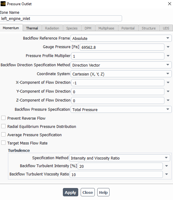
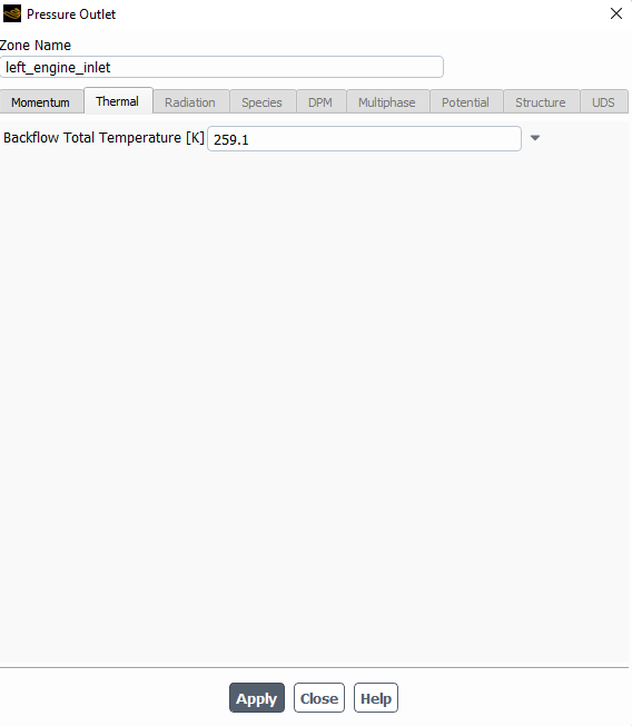
Engine Inlet: Pressure-outlet
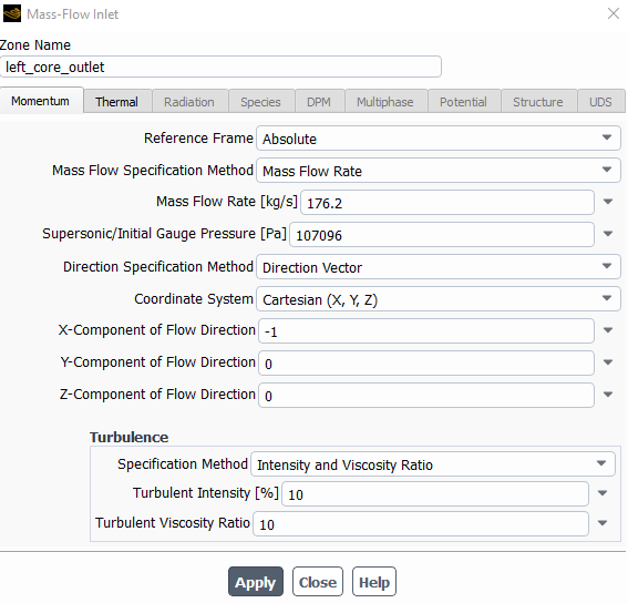
Engine Outlet (Core): Mass-flow Inlet
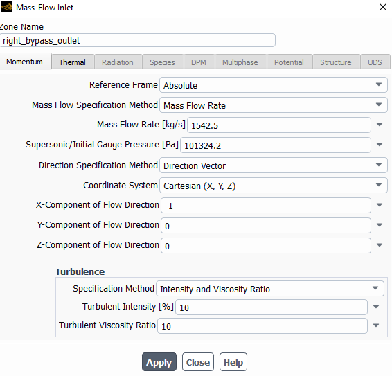
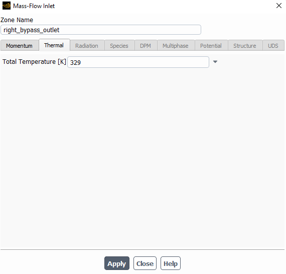
Engine Outlet (Bypass): Mass-flow Inlet
Solution method: Coupled - Least square - 2nd order - Pseudo Time Method
Initialization method: Hybrid
Although I'm now having some satisfactory results, the exhaust contours are still higher than the expected, and I'm still getting reversed flow at engine inlets and some high residuals.
Thanks in advance!
-
May 19, 2023 at 11:12 am
Rob
Forum ModeratorUnless you're adding swirl I'd leave "normal to boundary" for the directions. I'd also review using massflow outlet on the engine intake. The far field (pressure) boundary will deal with any mass imbalance.
-
May 19, 2023 at 1:08 pm
ricardo.pferreira
SubscriberHi Rob,
Thanks again for your suggestions.
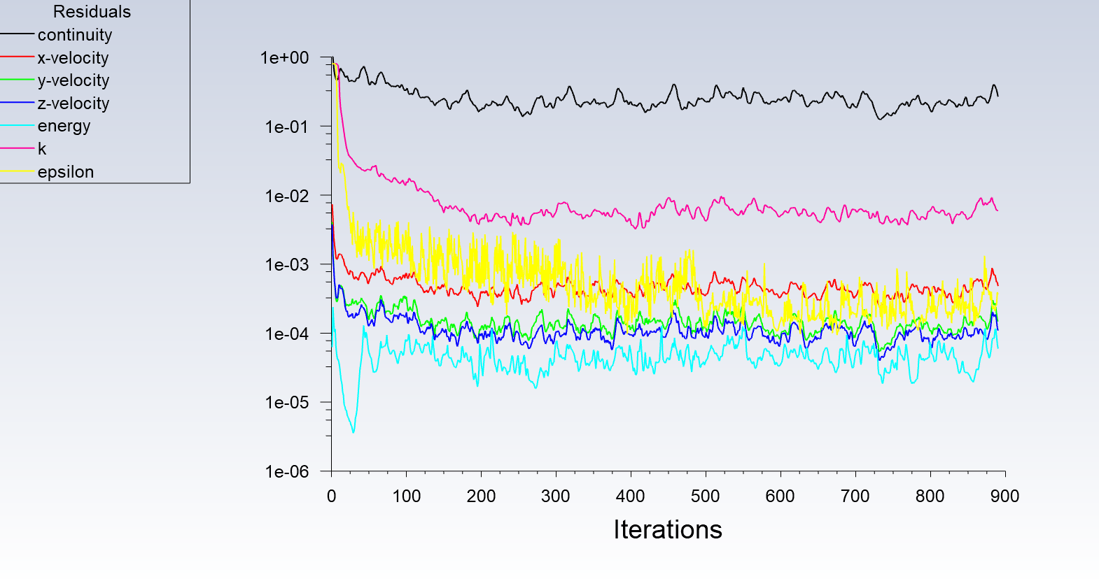
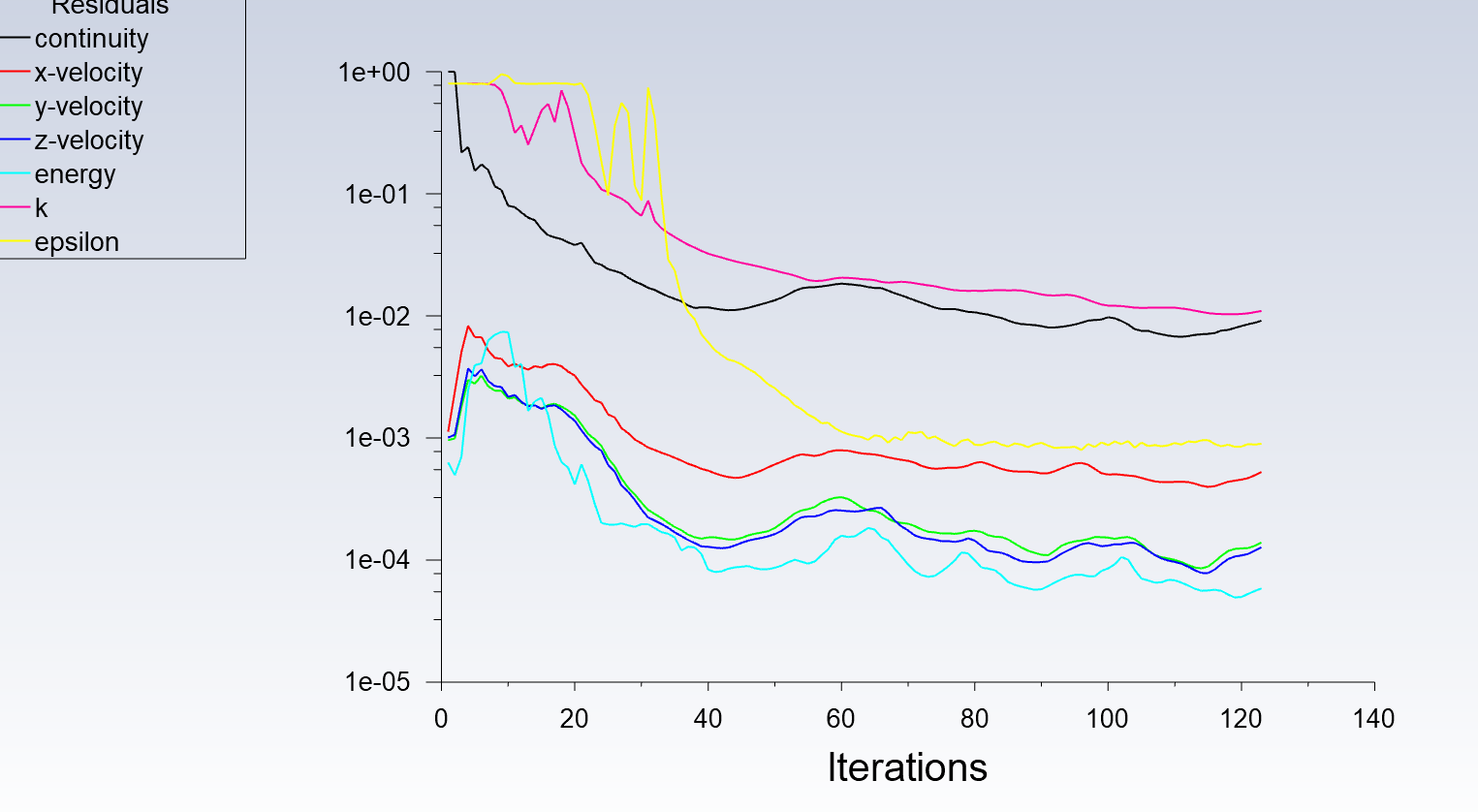
After configuring (and running around 1k iterations) as you suggest, the residuals are still not looking good:
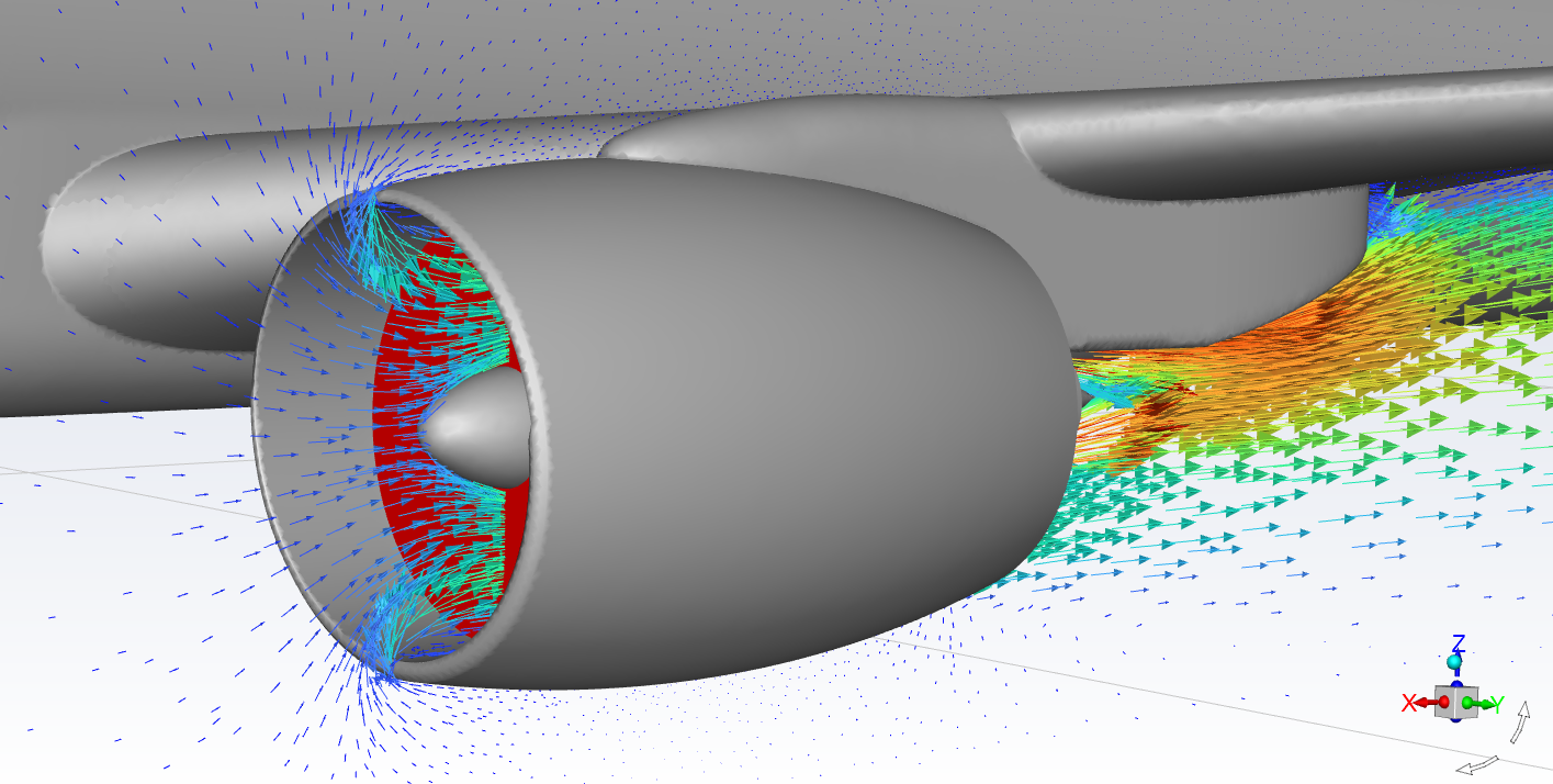
There are still some reversed flow at the inlets as well as high values of turbulent viscosity ratio. The min orthogonal quality after the conversion to poly is 0.41. Do you have any other suggestion that may help improving results?
Thanks again!
-
May 19, 2023 at 1:23 pm
Rob
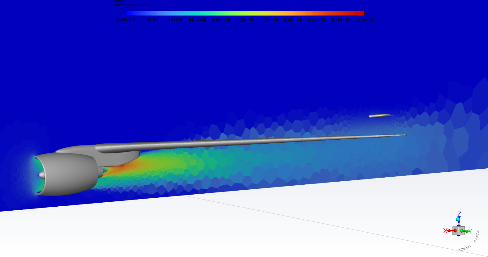
Forum ModeratorLook at the flow field around the engine, and post some contour plots. Post with node values off as that'll help explain if there's a problem.
If you left the PBCS Courant Number at 200, try about 50: the defaut can be a little optimistic. What other flow boundaries are set? Specifically the "outside" bound.
-
May 19, 2023 at 1:43 pm
-
May 19, 2023 at 2:11 pm
Rob
Forum ModeratorIf the aircraft is taking off (moving) how are you accounting for that? Will that have any effect on the flow over the wing? If all the external boundaries are symmmetry where does the exhaust plume go?
Plume may need a bit more resolution, and you may want to think about monitor points in the jet exhaust region. How stable is the exhaust?
-
May 19, 2023 at 2:31 pm
ricardo.pferreira
SubscriberHi Rob,
Totally agree with you on the plume resolution, but I've deliberately decreased the resolution on this region to fine-tune the methodology.
The analysis is assumed to be a steady-state of the precise moment when a aircraft gets full power for take-off (just right before start moving).
Monitoring points would be a good idea to check the length of the plume for the given velocities at the exhaust (44, 22 and 15 m/s) during the analysis, thanks.
I'm now running an analysis considering the inlet outside bound as "Velocity Inlet", since I'll need to control the velocity at the inlet to replicate the wind. The outlet ouside bound is set as "pressure inlet", since any other is not performing well. Do you have any other suggestion on the outside bounds?
This is how the residuals are looking now (a bit better I guess):
Thanks!
-
May 19, 2023 at 2:38 pm
Rob
Forum ModeratorPressure should be OK for outside. You'll need to account for hydrostatic head on the outer boundaries: search for buoyancy etc on here as I've answered it a few times.
Remember what residuals mean, there's a reason we also use monitor points and fluxes to judge convergence.
-
May 19, 2023 at 3:38 pm
ricardo.pferreira
SubscriberHi Rob,
Not sure if the buoyancy is helping in this case.
Why am I getting reversed flow at the outlet outside pressure boundary? Is it normal?
Thanks!
-
May 19, 2023 at 3:56 pm
Rob
Forum ModeratorLooking at the nacelle, very likely. Try plotting x-velocity on the surface (global range off) to see what's going on.
If you mean downstream, look at how air is entrained by the jet exhaust.
-
May 22, 2023 at 1:56 pm
ricardo.pferreira
Subscriber -
May 23, 2023 at 1:20 pm
Rob
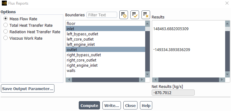
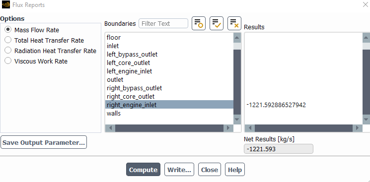
Forum ModeratorLook at the % difference/error. It's not ideal, but given the mesh resolution and domain size it's not too bad. This is why we use monitor points around the area of interest: the residuals aren't always enough to judge convergence. There's a reason why good CFD engineers are valued!
-
May 23, 2023 at 2:50 pm
ricardo.pferreira
SubscriberI'm really not focusing on the residuals, I'm just looking at the exhaust contours atm. The lengths of these contours are almost the double they should be. I'm assuming the boundary condition defined at the engine inlet (I've already tried both pressure inlet/outlet) is somehow messing up with the values at the engine outlet (either defined as pressure far field or mass flow inlet).
-
May 23, 2023 at 3:56 pm
Rob
Forum ModeratorWhy would it do that? Engine intake sucks out material based on it's setting, the engine exhaust is a mass flow bc?
-
May 24, 2023 at 1:56 pm
ricardo.pferreira
SubscriberHi Rob,
As said above.. I've already tried both mass flow inlet or pressure far field for the engine exhaust, but it is still not working.
-
May 24, 2023 at 2:18 pm
Rob
Forum ModeratorPressure far field on the engine will likely cause problems. Mass flow (sucking and blowing) should work well, but it's not clear what's not as expected. Convergence is a matter of residuals but also monitors: just because the boundaries are steady it doesn't mean the flow is.
-
May 25, 2023 at 8:38 am
ricardo.pferreira
SubscriberHi Rob,
I've finally discovered what's having a huge impact on results... It seems that the jet exhaust velocities more than double up when changing to Momentum - Second Order Upwind. However, when using the Momentum - First Order Upwind, values stay a bit lower than the expected.
-
May 25, 2023 at 10:37 am
Rob
Forum ModeratorWhich is a convergence issue. Given first and second order solutions tend to become similar on well refined meshes testing on a coarse mesh may not have been ideal.
-
- The topic ‘Aircraft engine flow exhaust’ is closed to new replies.


-
3402
-
1052
-
1051
-
896
-
872

© 2025 Copyright ANSYS, Inc. All rights reserved.

