

TAGGED: cfd, fluent, fluid-dynamics, fluid-flow, setup
-
-
April 22, 2022 at 6:15 pm
elisio
SubscriberHi!
I aim to simulate forced air through ducts and evaluate pressure drop (at dampers) and evaluate the air flow distribution over the outlet region.
Outlet geometry will be studied to distribute "equally" air through plenun chambers.
After results, evaluate pressure (for diferent inlet velocities) to size the fan needed to overcome the pressure loss.
My attempt is:
1- forced air flow through dampers;
2- forced air flow through dampers + exhaust system;
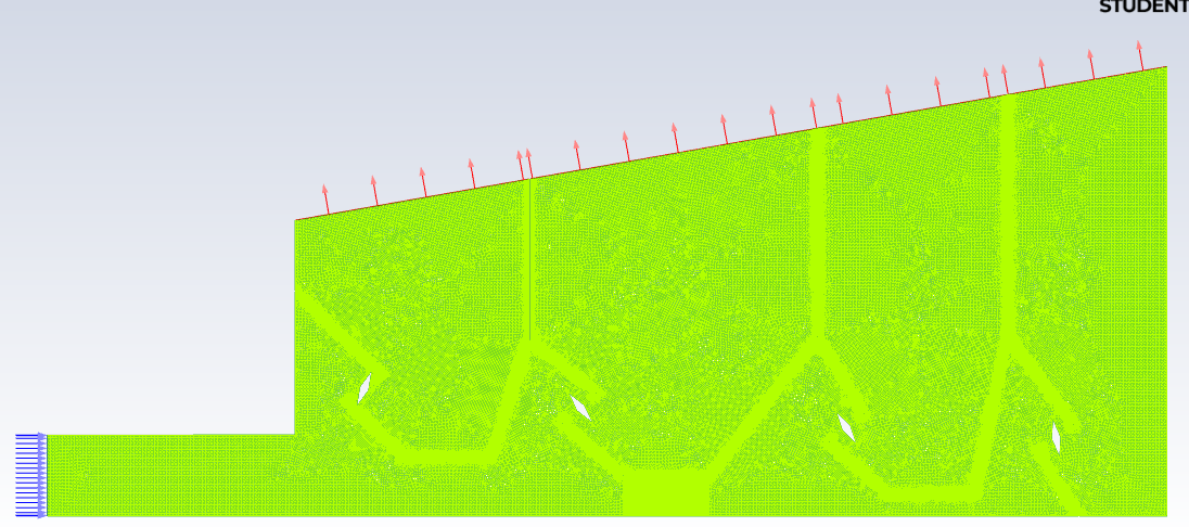
Figure 1: Duct + Dampers + windbox
April 25, 2022 at 3:53 pmRob
Forum ModeratorThe result looks sensible. If you push air in it'll adjust the mass flow to each section such that the pressure drop is the same. If you want a uniform extract set the inlet as a pressure boundary and use a velocity outlet (or negative velocity).
Why don't you think you should have the result you're seeing?
April 25, 2022 at 7:48 pmSubscriberBeing fair, i've already seen this system working, and it works together:
1 - forced air inlet (forced draft fan);
2 - exhaust air outlet (exhaust fan);
As you said, pushing air it''ll adjust mass flow to each section because of pressure drop caused by different dampers positions (flow area), but after entering each section, it should distribute air over all the chamber to, then, go out through all outlet region (edges at Figure 1 - red arrows). What i see, at Figure 4, is air flowing out near the wall only, at located region, while recirculation zone exists at most part of it, and air is comming in). Why air isn't flowing out? That's why i don't think it's right.
I aim to optimize pushing air through all exists, like choosing best damper positions (or/and flow rate or/and pressure required)
For uniform extract, i should set inlet as pressure boundary (not velocity inlet) and use velocity outlet (instead of pressure outlet). But i didn't realize how to do both together yet (push and exhaust), i believe (if it's possible) i could achieve a best air flow distribution through all edges region (red arrows - Figure 1) if it could be done. Or my setup ins't good enough.
Thank you in advance.
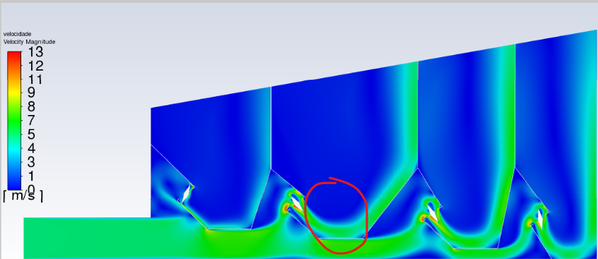
April 25, 2022 at 10:32 pmSubscriber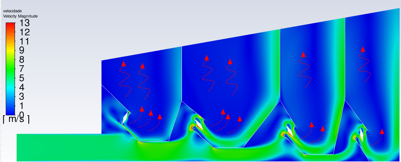 The image ilustrates what i (tried to) explain on the other comment. The blue region has vectors downwards instead of flowing out (making my section filling with air).
April 26, 2022 at 8:30 amForum ModeratorYou'd explained what you wanted to see, but not the why. You're actually modelling something quite complicated, and it's not covered in under-grad courses. The fact you've picked up the feature and are questioning the result is good. Why should the jet detach from the wall and spread? Have a look at the Coanda effect, and also think what's on the end of the domain, ie where does the flow go after the manifold?
April 26, 2022 at 10:59 amSubscriberSince my outlet region was supposed to be at same exhaust pressure - let's say -200mmH2O -, i'd expect air deatching from the wall and filling each section, going upwards (not recirculating) reaching a bigger chamber (which is not in domain). That's why i asked about pushing and exhaust air at the same Volume Control.
Explaining this, maybe i should extend my domain to avoid these recirculation shown at Figure 4. Rob, What would you consider wise to my case: 1- set inlet as pressure boundary or 2- set outlet as pressure boundary? 3- simulating both and check results.
By the way, what are preferential tools to avoid recirculation / making my outlet region exit? Extending domain?
April 26, 2022 at 2:11 pmForum ModeratorExtending the domain is the usual method to avoid recirculation, but you also need to consider what happens in reality. Ie if the system vents to atmosphere then you may find the real system also behaves in this way. If there's a downstream flow restriction (eg a filter) the chamber my pressurise to some extent which will even the flow out. If you check the flow split over the four sections it'll not be even, again that may well be correct.
I wouldn't use a pressure in & pressure out in this case as the solver will mass flow AND split will become part of the solution. The end result will be much as you have in the above but getting there will be painful.
April 27, 2022 at 10:41 amSubscriberI agree mass flow will be different at each section, but i am not sure about those localized outlet vectors (caused by coanda effect). I will create my restrictions at each outlet section (and extend it) to evaluate its behavior.
After all these points, i believe BC should be velocity inlet + pressure-outlet, which should works fine.
Did ANSYS create new "ANSYS Fluent Tutorial Guide" for 2022?
Thank you so much for your comments and help, Rob.
April 27, 2022 at 12:47 pmForum ModeratorI think we just updated the 2021R2 version. We are adding more content to the Courses and (paid for) training materials but I don't know the plans in detail, and couldn't share if I did!
Flow in manifolds is a complex area of study, and most overlook this fact. Adding further pipework/filters etc to the manifold then changes the flow splits. My PhD took advantage of flow balancing based on the "area" of a port, and I know from doing that work that whilst it's obvious when you know why, that it's anything but when you're learning!
April 29, 2022 at 10:57 amSubscriberOk Rob, discussing these issues help me a lot! Thanks for all information and explanation.
In fact i'd like to understand more about air/gas flowing, blowing, pressure drop, restrictions, ducts... That's the reason i am simulating this kind of fluid flow. As you said, people overlook this, because it's "simple" compared to the rest of the complete system. Since you are professional with applied works and a lot of knowledge (simulation + physics), if not asking too much:
1- I set up velocity inlet (18m/s - 100mmca pressure gauge), if i don't set this pressure (empty field) ANSYS return me a pressure. This pressure is only based on velocity or velocity + cross area?
2- To obtain the constant "k" of pressure drop across the damper (dP = K.v┬▓/2g) i should evaluate static pressure (or total pressure?) before and after damper, but since my velocity changes, should i use mean velocity?
3- Evaluating total system pressure drop, is it right just measuring (total pressure) an outlet point less inlet point ?
4- Creating a turbulent flow at marked area, coanda's effect should be minimized, right? I mean, increasing velocity/ mass flow to collied at wall and mess up to "distribute" the fluid to section.
Thanks again, Rob.
April 29, 2022 at 4:17 pmForum Moderator1) If you have a velocity inlet the pressure is only used if it's supersonic: at 7m/s it probably isn't!
2) dP = 1/2 rho v2 Not sure what the K value is, but I suspect it's static pressure. Read the section on Porous Media in the Fluent User's Guide, I think that's what you're after. I've forgotten a lot of the basic fluids theory and rely to remind me. He's much younger....
3) Use the area average values, point values can be misleading.
4) Not sure what you mean. If you want to spread the jet out you may want to look at venturi nozzle theory.
May 3, 2022 at 5:41 pmSubscriber1) OK. From that I presume pressure showed at results is 100% in function of velocity.
2) OK. K is a "fitting factor" used to correct Dynamic Pressure when fittings are present (valves, dampers, curves...). So from dP = rho v2 K * 1/2, K can be estimated measuring dP and v (which idk if mean velocity is correct way).
3) OK, agreed.
4) I mean injecting a lot of air which could hit that corner deflect air to the middle of section chamber instead of flowing to wall (coanda's effect).
Thanks again, Rob.
May 4, 2022 at 10:19 amForum ModeratorIf you want to spread the air into the manifold zones more evenly you need to look at the entry system. You're currently forcing flow to turn through the valve(?) assembly, but then not doing anything to encourage jet spreading.
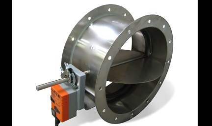
May 4, 2022 at 11:06 amSubscriberFlow is passing through a butterfly damper (flat plat), like the image below:
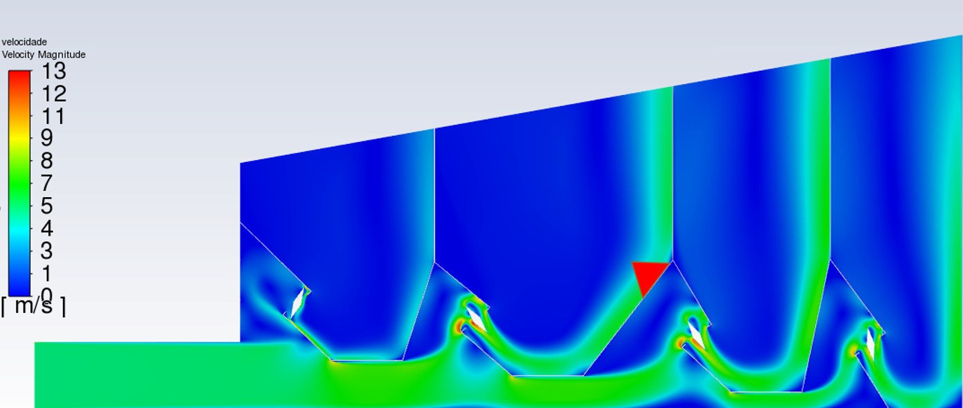
 As you can see at Figure 1, dampers are represented by hollow diamonds, each section has different dampers positions. Velocities are high at these restriction, it forces air flowing directly to wall (but not spreading to chamber after hitting it). I will try two ways:
1 - Setting lower/higher speeds at damper to monitor coanda's effect over the wall. By physics, theres a inflection point which it shouldn't occur anymore, right?
2 - Assembling some kind of deflectors (red triangle):
May 4, 2022 at 11:31 amForum ModeratorThere is a point where the jet won't form, but that'll be a very low speed. Jet sticking, Coanda effect etc are why certain fluidic devices work, and where my PhD supervisor spent his academic career & it's still keeping him out of (some) mischief now he's retired.
A deflector may work, as may a diffuser. That's for you to discuss with your supervisor. We (staff) are only supposed to help with the software questions.... Of course when you model it you'll find out.
Viewing 14 reply threads- The topic ‘Air flow and Exhaust System – CFD windobox’ is closed to new replies.
Innovation Space Trending discussions
 Top Contributors
-
peteroznewman
 6520
6520 -
scabo
 1906
1906 -
Dennis Chen
 1463
1463 -
javat33489
 1310
1310 -
Shyam Prasad V Atri
1022
Top Rated Tags
© 2026 Copyright ANSYS, Inc. All rights reserved.
Ansys does not support the usage of unauthorized Ansys software. Please visit www.ansys.com to obtain an official distribution.
-


The Ansys Learning Forum is a public forum. You are prohibited from providing (i) information that is confidential to You, your employer, or any third party, (ii) Personal Data or individually identifiable health information, (iii) any information that is U.S. Government Classified, Controlled Unclassified Information, International Traffic in Arms Regulators (ITAR) or Export Administration Regulators (EAR) controlled or otherwise have been determined by the United States Government or by a foreign government to require protection against unauthorized disclosure for reasons of national security, or (iv) topics or information restricted by the People's Republic of China data protection and privacy laws.
