Ansys Assistant will be unavailable on the Learning Forum starting January 30. An upgraded version is coming soon. We apologize for any inconvenience and appreciate your patience. Stay tuned for updates.
Fluids

Fluids

Topics related to Fluent, CFX, Turbogrid and more.

Acoustics for muffler

    • Danielgkh
      Subscriber

      Hi,

      I am running an acoustics simulation on a muffler for a 3 cylinder engine in Micro-CHP. I am interested in the sound pressure level at the muffler outlet, especially for the low frequency range. Acoustics caused by the muffler itself is ignored as I am only interested in the noise created by the air flow. There is a big temperature difference between outlet and inlet as the muffler is connected to a heat exchanger. I am using mass flow inlet as that's the only known parameter to me. I am using realizable k-epsilon with enhanced wall, with incompressible ideal gas as fluid.

      1. Which acoustics model should I use? Since Ffowcs Williams and Hawkings doesn't work on noise propagation inside duct and wave equation require constant gas density, is Broadband a good/only choice for me? Or the direct method suits me better?
      2. For the inlet, must it be pulsating inlet? Can I use constant mass flow rate?
      3. If it needs to be a pulsating inlet, which kind of wave for the exhaust gas from the engine should I use? Sine, Triangle, Pulse? I will define a time-dependant function either with Fluent Expression or with profile file, with the former ones seems more promising.

      Thanks for the help. And feel free to point out any mistake that I made.

    • Marco Coderoni
      Ansys Employee
      Hello,
      For your case you may have two options to solve for the sound propagation:
      -Direct method, solve for a compressible fluid.
      -If the Mach number of the moving fluid is small, you can also use the Acoustic Wave Equation model, while solving for an incompressible fluid.
      The Chapter 15: Aerodynamically Generated Noise of the theory guide will give you more insight on the essence of the two methods.

      The answer to you other two question depends on the problem you are trying to reproduce. Is the inlet fluctuating? If so has it a specific wave form? The answer to these questions would give you an idea of what to use.
      As general comment I would suggest to use the k-omega model or the GEKO model for the viscous effects since less dissipative than the k-e model.
      Hope this helps
    • Danielgkh
      Subscriber

      thx so so much for the reply.
      I think I have made a mistake, my material should be compressible gas. Even though the gas velocity never exceed 0.3 Mach, there is big pressure difference (~2000Pa) inside the muffler as the gas pass from one chamber to another chamber through a narrow pipe.
      However, what does it mean by a direct aeroacoustics simulation? Is it just running normal transient simulation? There is not much info or tutorial on such simulation. And how do I activate/find/export the acoustics property for such simulation?
      I am interested to plot a graph of pressure versus time and also acoustics power level (dB) versus frequency of a specific point at the gas outlet. Almost like the case with FW-H Model by setting source and receiver, then using Fast Fourier Transformation for postprocessing.
      Any help is much appreciated. Thank you.
    • Marco Coderoni
      Ansys Employee
      Hello,
      You just need to set the air as compressible and run the transient case (with all the correct boundary conditions) to get your solution. There is no special set up you would need. Create points and then use them to set up monitors to collect the pressure data at the locations you need. Then you can do a FFT on the files you save as these monitors output.
      Hope this helps
    • Danielgkh
      Subscriber

      thank you very much for your help. However I still have some questions which I hope u can help me with.
      First, let me explain briefly how I ran my simulation.
      Steady state simulation using realizable k-e model, enhanced wall treatment, viscous heating. Ideal gas law for air density, polynomial for cp, thermal conductivity and viscosity. Operating pressure 1 atm, operating density 0 kg/m┬│. Constant mass flow rate for mass-flow-inlet(the only realworld value that I have). 0 pa gauge pressure at pressure outlet. Then run until it converge, or to a very low value.
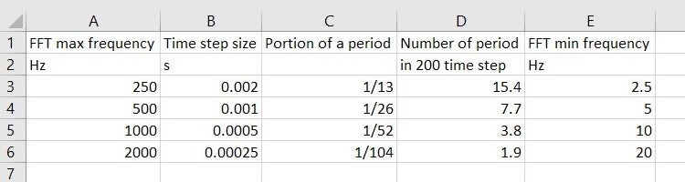
      Transient state simulation. Everything remained the same other than pulsating mass flow rate using transient table. Time step size 0.0002s. Save data every 5 time step, so every 0.001s, which FFT up to 500 Hz (0.5/0.001s).
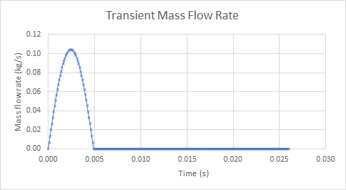
      Here is my transient mass flow rate. From here, I created a transient table and it has a period of 38.5Hz or 0.026s.
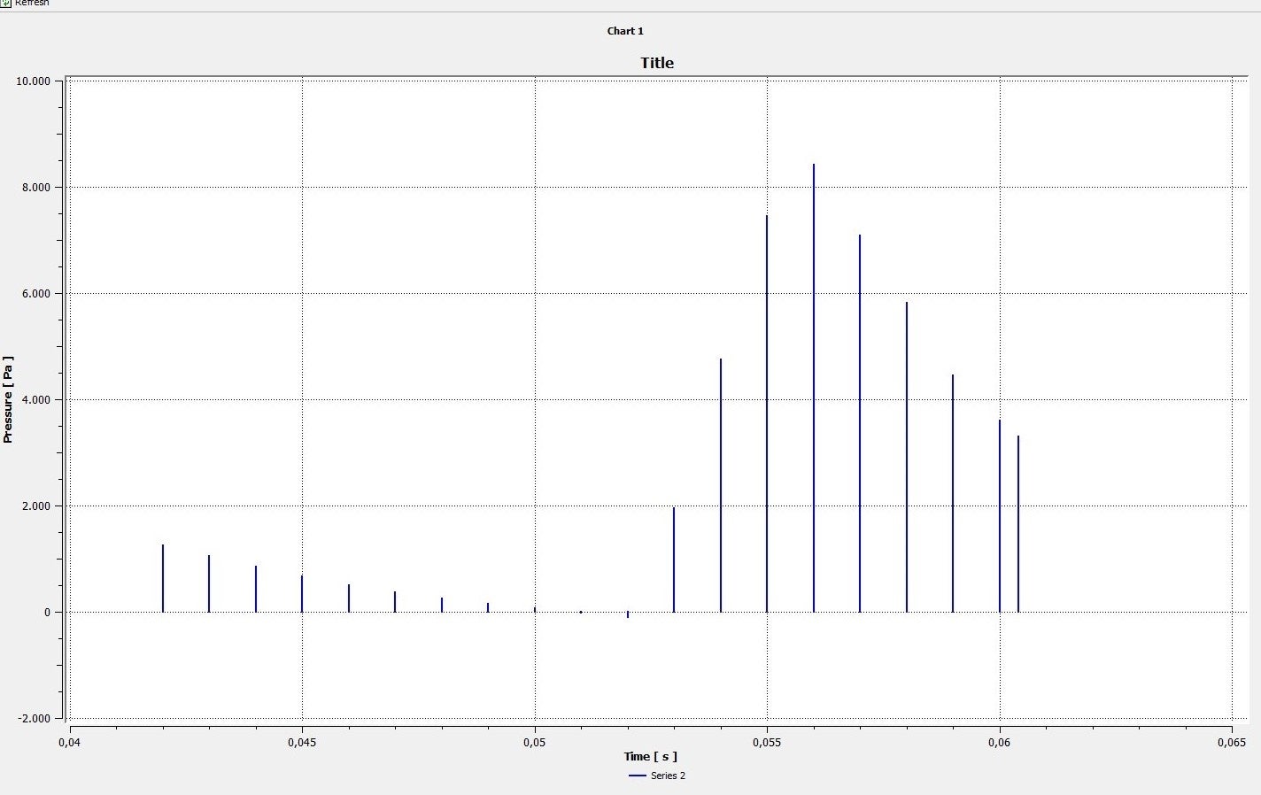
      Here are my results from CFD-Post. Series 1 is from outlet, series 2 is from inlet.

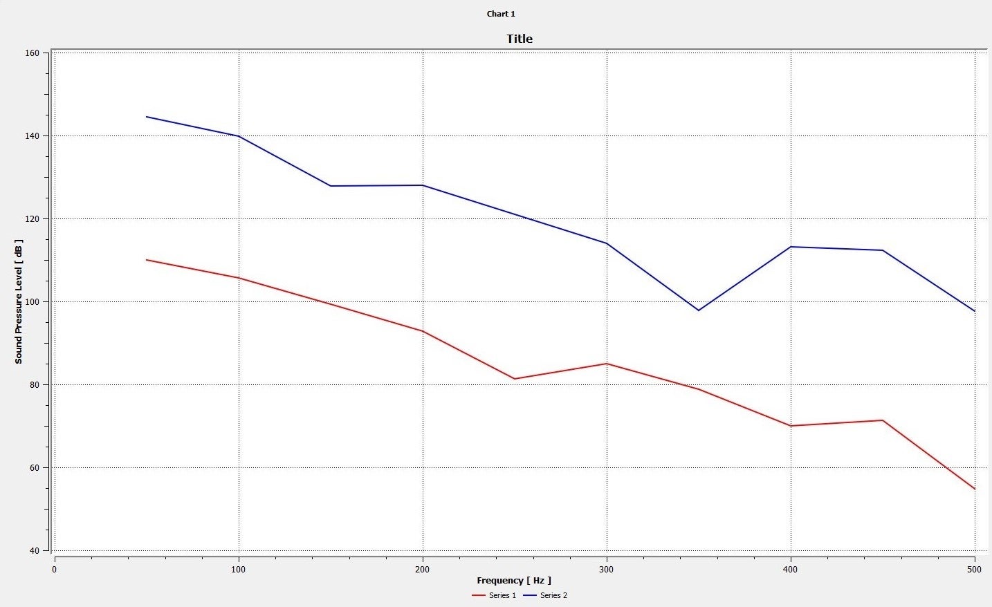
      Why is the SPL value below 40 Hz missing from the graph? Is this a problem of my periodic transient table?
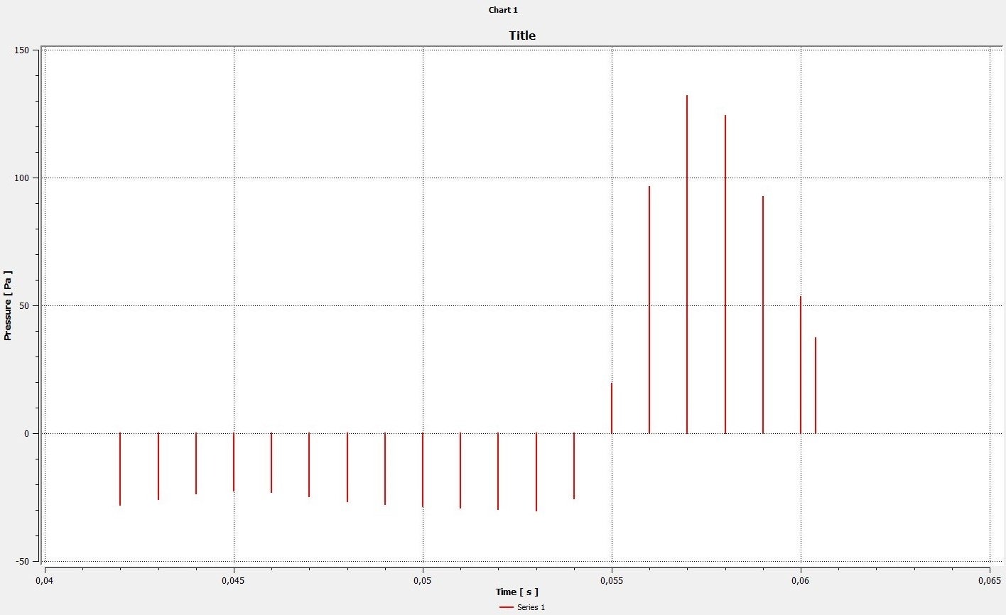
      Do I need to make any changes to the pressure value from simulation? Or I can use the pressure value computed and perfom FFT directly? 140 dB seems unrealistics.
      How do I increase the resolution of my SPL chart? It seems as if only one value is calculated every 50 Hz. Does accounting more period/cycle/"exhaust" improve the accuracy of SPL chart?
      Any suggestion or improvement on my simulation step is very much welcomed. Thank you.
    • Danielgkh
      Subscriber
      Hi I have found the answer to my 1st and 3rd question after checking up CFD-Post user guide. 2nd question is still buggling me.
      And also, in the case where I am much more interested in the low frequency range (<250Hz), which time step option should I go for? Since I have limited memory capacity, 200 time step is the most I can saved, as it is gonna take up around 50 GB of space. What is actually the best prectice for such selection?
      Please advise me on this matter. Thank you in advance.
    • Marco Coderoni
      Ansys Employee
      Hello,
      Assuming that you are exporting data every timestep, then your timestep would define the frequency resolution (delta f) of the signal. The overall period of sampling (T) defines the lowest frequency you can resolve. The smaller is the frequency you need to study the longer is the period for which you need collect data.
      To reduce the amount of data you save, just select the few location you are interested in. For example, if you need to study only two points in the domain, do not export the full 3D data, but just the pressure signal at that location. You can create a point and use just that as monitor.

      Hope this helps


Viewing 6 reply threads
  • The topic ‘Acoustics for muffler’ is closed to new replies.
[bingo_chatbox]