TAGGED: mechanical, ratio, shell-elements
-
-
May 20, 2022 at 1:40 pm
piknockyou
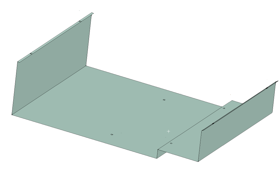
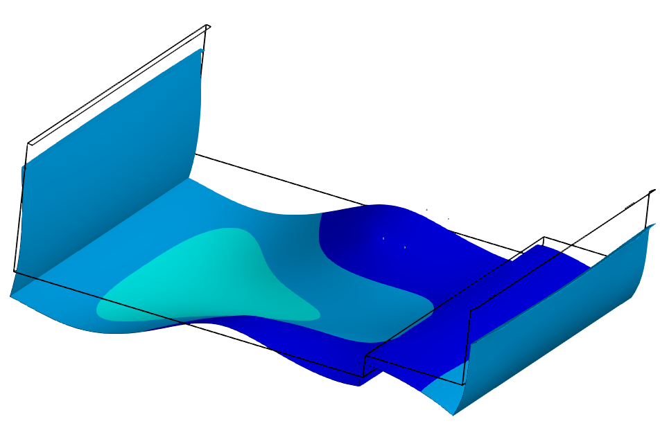
SubscriberI'd like to simulate the deformation of a sheet metal with a large width/length to thickness ratio, for example this:

 For fidelity comparison of separate 3D simulations, we consider using different quadratic element formulations:
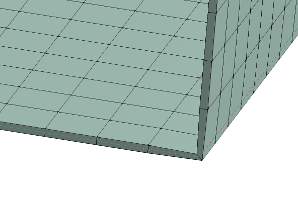
Solid elements (1 Layer; Hexaeder dominant)
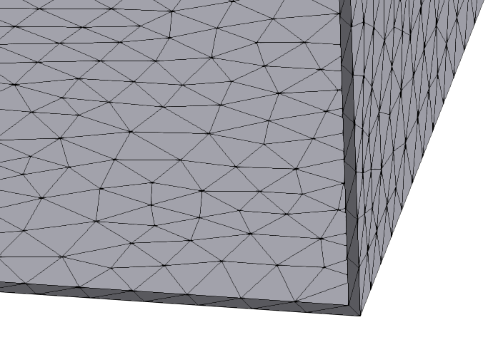
Solid elements (1 Layer; Tetraeder)
Shell elements (Quad dominant)
Solid-Shell (1 Layer)
Not limited to this problem, but in general:
What is a (still) acceptable Element-Edge-Length-to-Thickness Ratio for each case to not largely deviate from the "real" deformation behaviour & magnitude (maybe max. 3 %)?
Is the ratio the same for all quadratic element formulations listed?
Beside "hard guidelines", I would also appreciate, if you shared your experience stating, what you "feel" is acceptable.
I have no clue, just a feeling based on not much.
10 to 1 maybe?
How does this look?
 Or this?
 Thank you!
-
May 24, 2022 at 12:17 pm
Chandra Sekaran
Ansys EmployeeWith solids the number of elements thru the thickness is probably more important for bending type applications while maintaining reasonable aspect ratio like 10. There are studies out there if you Google for shells vs solids like this one I found by Googling. https://imechanica.org/files/AnsysShellCompare_1.pdf
-
Viewing 1 reply thread
- The topic ‘Acceptable Edge-Length-to-Thickness-Ratio for deformation evaluation?’ is closed to new replies.
Ansys Innovation Space


Trending discussions


Top Contributors


-
3597
-
1283
-
1117
-
1068
-
983
Top Rated Tags


© 2025 Copyright ANSYS, Inc. All rights reserved.
Ansys does not support the usage of unauthorized Ansys software. Please visit www.ansys.com to obtain an official distribution.


