We have an exciting announcement about badges coming in May 2025. Until then, we will temporarily stop issuing new badges for course completions and certifications. However, all completions will be recorded and fulfilled after May 2025.
LS Dyna

LS Dyna

Topics related to LS-DYNA, Autodyn, Explicit STR and more.

A question about using shell and solid elements together

    • Andres.Mena
      Subscriber

      Hello,

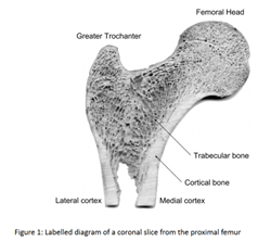
      A summary about the origin of my questions.... Trabecular bone and cortical bone usually have the following layout in long bones:

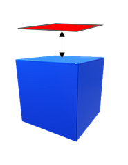
      Since trabecular bone is a major part of the bone it is normally modelled using solid elements. Cortical bone is a relatively thin layer on top of trabecular bone so it's possible to model them using solid elements as well with certain care.

      However, I've noticed a particular modelling technique for cortical bone in lumbar spine FEA models involving using shell elements on top of solid elements so I guess they share nodes (Bowden et al. 2007 10.1016/j.clinbiomech.2007.12.010). I am aware that there is certain interaction between solid and shell elements in mesh transitions that is well documented like this one /forum/forums/topic/interface-between-solid-and-shell-elements/)

      But what happens exactly when you build shell elements on top of solid ones? Is this recommended or not?

      I couldn't find much information apart from skins or membrane elements in other software, so I have some questions I hope someone has some experience with:

      • From what I understand, solid elements don't have rotational DOF so only translational DOF are shared, right? If both elements have default LS DYNA element formulations is it okay to use nodal averages for the surface?
      • The nodes used to construct a shell element are placed in the shell midplane, so what would happen with the half thickness being projected inside the solid element? Is there a way to project the thickness completely in one direction rather than half and half?
      • Does this technique have any implications with regards to contact (basically frictionless automatic surface to surface with SOFT=0)? The difference in young's modulus between trabecular-solid (E=300 MPa) and cortical-shell is significant (E=12 000 MPa).

      Thanks,

      Andres

    • Aniket
      Forum Moderator

      Hi Andres,

      Is your analysis using Workbench LS Dyna or Ansys Mechanical?

      -Aniket

      How to access Ansys help links

      Guidelines for Posting on Ansys Learning Forum

    • Ashish Khemka
      Forum Moderator

      I think Erik answered it: Interface between solid and shell elements (ansys.com)

      Regards,

      Ashish Kumar

    • Andres.Mena
      Subscriber

      Hello! I am using LS Dyna (with LS PrePost).The reason I posted the Ansys forum answer is because a hinge-type structure is explained there, but I couldn't find much information when you do something like building a shell element on top of a solid one like this:


      Sorry if the ansys interface question caused any confusion.

    • Jim Day
      Ansys Employee
      Short answer is that it's OK for shells and solids to share nodes. The rotational DOF of the nodes aren't used by the solid elements. Since this entails having nodes on the inner surface of the shells, use NLOC in *SECTION_SHELL accordingly and set CNTCO in *CONTROL_SHELL so that the contact recognizes the offset of the shell given by NLOC. To avoid uncertainty of how contact stiffness is calculated in this shared node situation, I'd just use SOFT=1 or SOFT=2.
    • Jim Day
      Ansys Employee
      To clarify, set CNTCO to 1. NLOC will be +1.0 or -1.0 depending on how the shell normals face. You can check location of shells by reading the keyword file into LS-PrePost and selecting Model>Appear>Thick>All. The shells will appear as solids with shell thickness shown.
    • Andres.Mena
      Subscriber

      Hello Jim,

      Thank you for your answer! I will determine the appropriate NLOC value based on what you told me. I suppose nodal averages would account for adjacent solid elements and the shell one on top, right?

      Since you said short answer, can you recommend me any references to find more information on different element types sharing nodes? I couldn't find much


    • Jim Day
      Ansys Employee
      Please rephrase or elaborate on your first question.
    • Jim Day
      Ansys Employee
      My "short answer" was meant to address only the case where the shells lay flat on the solid surface as shown in your figure.
    • Jim Day
      Ansys Employee
      "Other element types sharing nodes" is too broad a subject. State what other particular situation of elements sharing nodes that you have in mind.
    • Andres.Mena
      Subscriber

      My apologies, I will rephrase the latter questions in new threads as they were too broad. 

      A different question regarding NLOC and contact. Does the value of NLOC affect the location of the shell elements (and solid ones) and thus which one contacts another body first or is this just for visualization purposes? What I am trying to simulate is a layer with shell elements that should interact first with another body since they are on top.

      Thank you

    • Jim Day
      Ansys Employee
      With variable CNTCO set to 1, the contact will recognize that the shell reference surface is offset (due to NLOC) and the contact surface for the shell will be located accordingly. If CNTCO is left as default (0), the contact algorithm won't pay any attention to NLOC. Hope that's clear.
    • Andres.Mena
      Subscriber

      I understand, thank you. Just out of curiosity, if CNTCO was set to 0 and the offset is ignored, what would happen to a contact algorithm SOFT=0? Would the shell elements still be the ones interacting with another body?

    • Jim Day
      Ansys Employee
      The shell contact surface would still be offset from the reference surface by half a contact thickness (contact thickness = shell thickness unless overridden by variables on Card 3 of *CONTACT). Thus the shell contact surface would encounter another body first. If excessive penetration of that contact surface is observed, possible remedies would be to increase the contact thickness and/or increase the contact stiffness (see Card 3 of *CONTACT).
Viewing 13 reply threads
  • The topic ‘A question about using shell and solid elements together’ is closed to new replies.