-
-
May 15, 2024 at 11:28 am
Pedro Miguel Gonçalves
SubscriberHi,
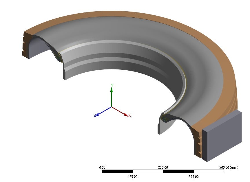
I`m currently finishing my master's degree thesis in mechanical engineering and to accomplish that i am simulating tire inflation and compression against the floor in a 3D model shown above:
The tire is composed of 5 hyperelastic materials and the others are linear. The floor is made from structural steel to make some simplifications. I have symmetry in the model, normal to the Y and the X axis.
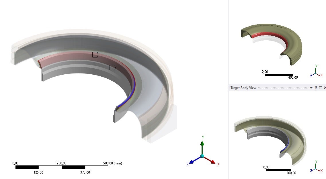
The contact region between the tire/rim is set to frictional 0.3, following the literature review and the contact between the tire and the floor is frictionless as shown in the images:
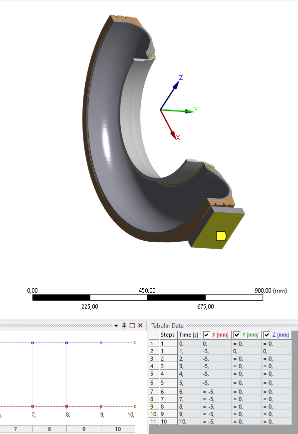
To start the 3D simulation i need to initially inflate the tire from 0-0,43 MPa in the first 2 steps ( That´s why the floor is not close to the tire, having an offset distance of 5 mm ( To ensure that the tire inflates without touching the floor)).
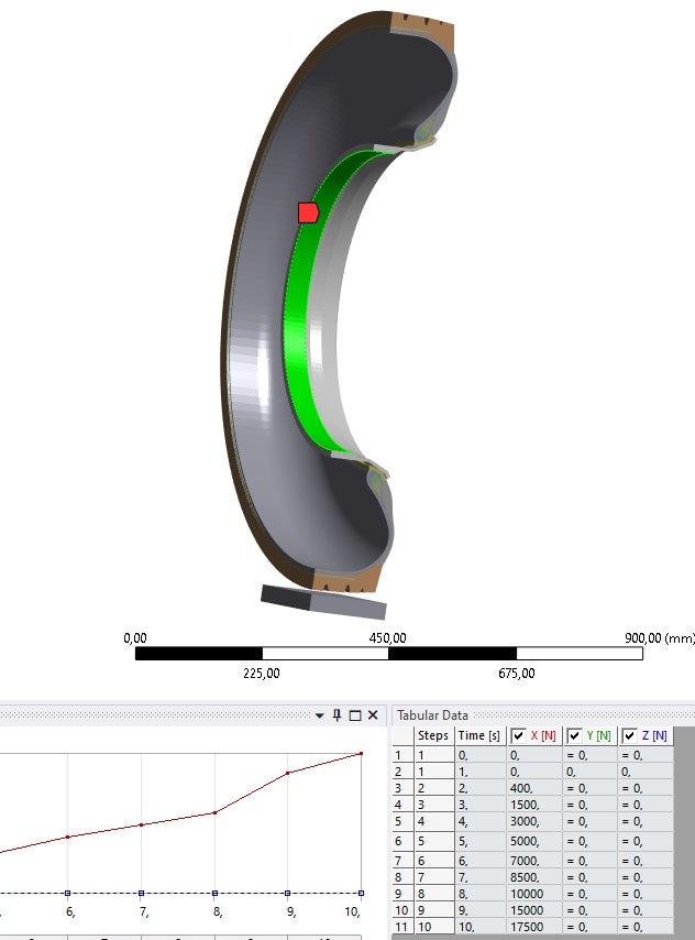
After inflation, I set a step and displacement that moves the floor in (- X) direction to make contact between the tire and the floor, and then, in the next steps I apply the load in the rim (X direction) from 0 - 17 500 N in several steps to simulate the vehicle load.
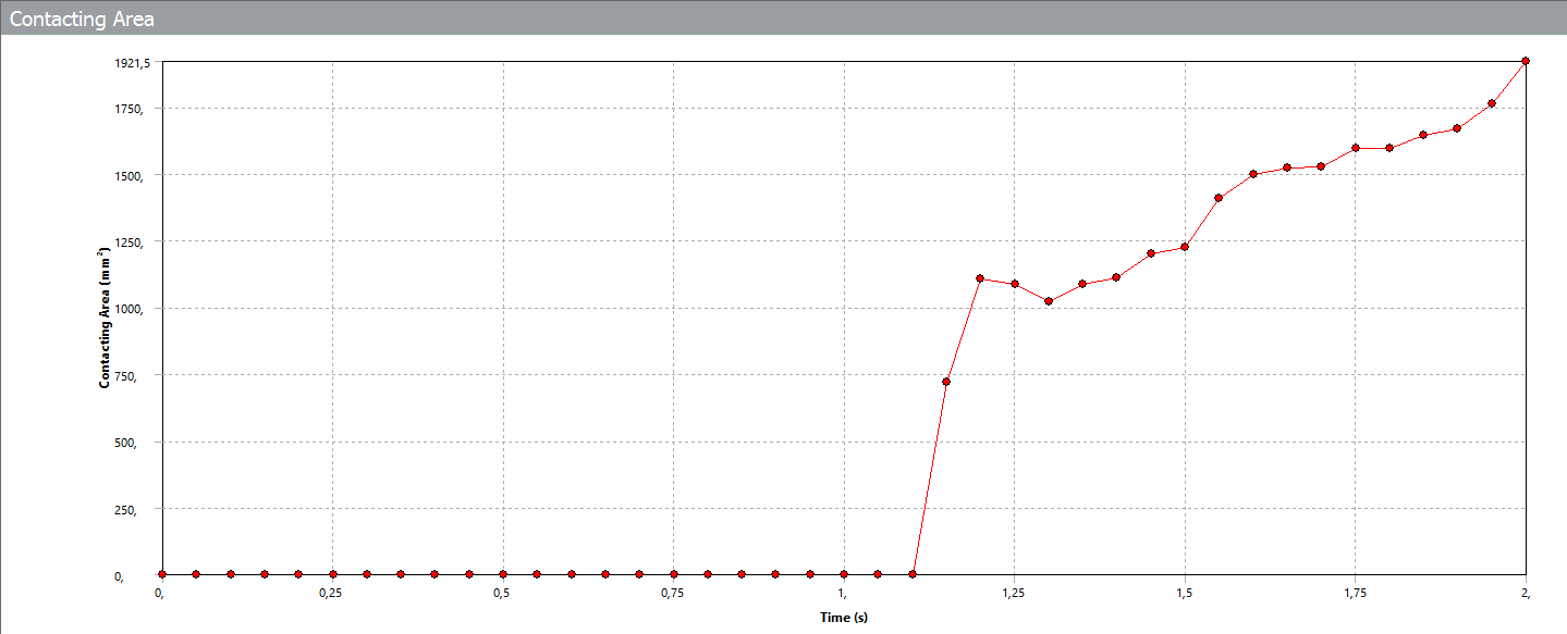
I need help in this simulation since I´m having trouble with conversion in the load steps. I think it is related to something like When the tire is fully compressed against the floor, at a certain instant, the contacting area between the tire and the floor should stop increasing and reach an equilibrium, and it doesn't and crashes because of no convergence at this point. Can anyone help me?
PS: - I´m using Large deflection because of the hyperelastic materials
- Weak springs to ensure that the tire does not move when I apply the displacement in the floor to detect the ( Tire Floor) contact
- Quasi-static solution ( to simplify the model complexity )
- 2 symmetric regions to simplify the model
Load placement picture:
As you can see, the tire makes contact almost in the final of the 2 step and then, the load is applied in the rim
Can someone help me solve this problem? I want to finish this simulation to finally be able to study the deformation fields in the tire after loading with the correct data. I´ve been trying to make it work for more than a year !!!
PS: The picture only shows until 2 seconds because I´m currently simulating again, normally it stops at step 6...
How can I ensure conversion in this type of scenario? I don't want to evolve to a Dynamic Simulation because it is much more time-consuming, I want to solve it in a static structure model0.
-
May 15, 2024 at 12:24 pm
Pedro Miguel Gonçalves
SubscriberIn the article that i been following they used Abaqus but i want to make it work using Ansys.
Here is an extract of important information of the article:
"The first step of the finite element tire–pavement contact surface simulation is the
pressing of the tire model onto the road pavement. To achieve convergence, it is practical
to give a predefined shift for the clamping of the tire, as a boundary condition, until the
establishment of the contact. In the beginning, the distance of the tread of the inflated tire and the road pavement was 2 mm. The predefined shift was chosen as 6 mm, and about 1600 N counterforce in the boundary condition. "How do i put a predefined shift on Ansys ?
How can i apply that 1600 N counterforce ?
-
- The topic ‘3D Tire Simulation using Static Structure – Help’ is closed to new replies.


-
3467
-
1057
-
1051
-
918
-
896

© 2025 Copyright ANSYS, Inc. All rights reserved.

