
-
-
March 16, 2021 at 7:45 pm
nmarkiz
SubscriberHello,
I am trying to simulate a 3 point bending test on a Beam with the following dimensions: L= 125 mm, W= 12.7 mm and T=3.2 mm.
the span length is 51.2 mm ( the distance between the 2 supports).
I took the advantage of symmetry and draw my geometry in space claim as following:
Here the length of the beam is 62.5mm.
March 16, 2021 at 8:01 pmpeteroznewman
SubscribernI see the orthotropic material has lower stiffness in the Z direction, which I assume is the build direction. What direction was your beam built in? I expect it is the Y direction. That means the material orientation doesn't match the part orientation. A simple fix would be to swap the Y and Z values in Engineering Data.nTwo elements through the thickness is not sufficient for a good resolution of stress values. Change the mesh method to sweep so that you can use large element edge lengths along the length and width, but set the number of sweep elements to 8.nTry replacing the Remote Displacements with Displacement BCs on the two edges.nWhat results are desired and why don't the results you obtained satisfy the desired results?nMarch 16, 2021 at 9:20 pmSubscriberHi Peter, nThank you for your response.nWell I didn't print my beam yet, however I have the previous orthotropic material properties. My friend did the simulation using ansys APDL where he used 3 solid rods, 2 as supports and one as pusher and the support is far 20mm from the origin. he got the following resultsnDeformation in Y n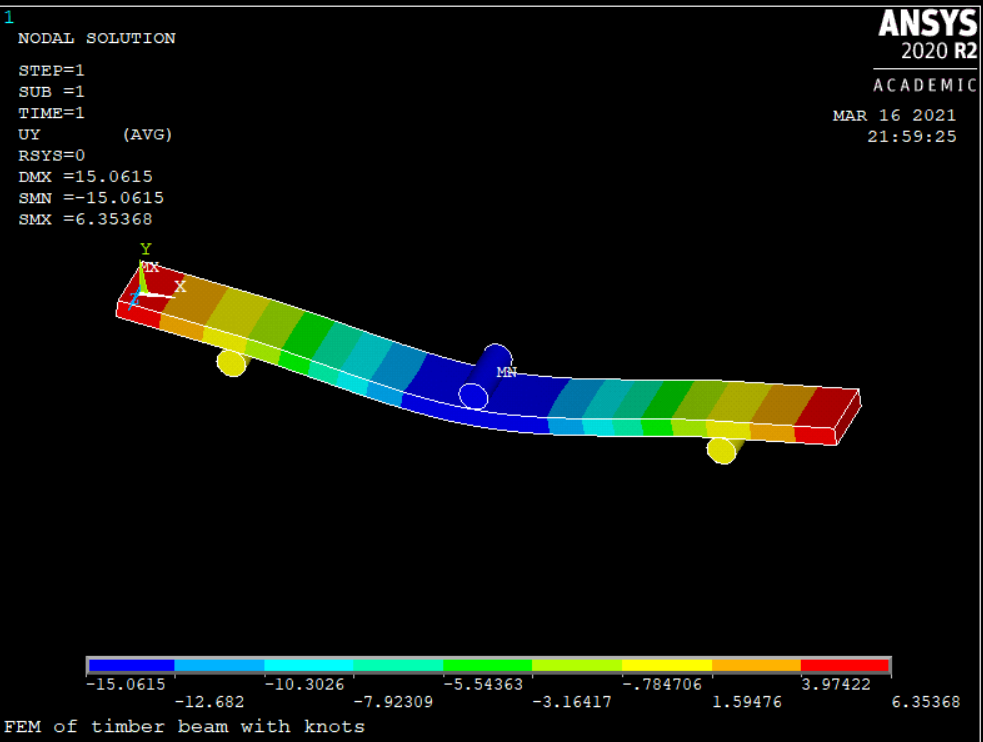 nStress in Xnn
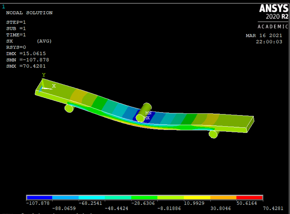 nVon misses Stressnn
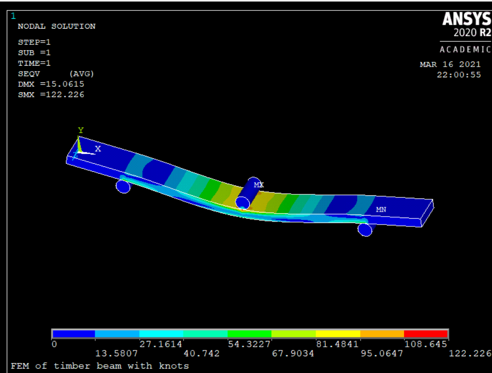 nI draw the geometry again and split the face 20 mm from origin and made a sweep mesh as u suggested. I applied Displacement as Boundary conditions. I want to match my results on workbench with Mechanical APDL. But unfortunately, I couldn't got the same results.nHere is the sweep method, however the generate the mesh with default element sizen
 nnHere are the 2 Boundary conditions:nn
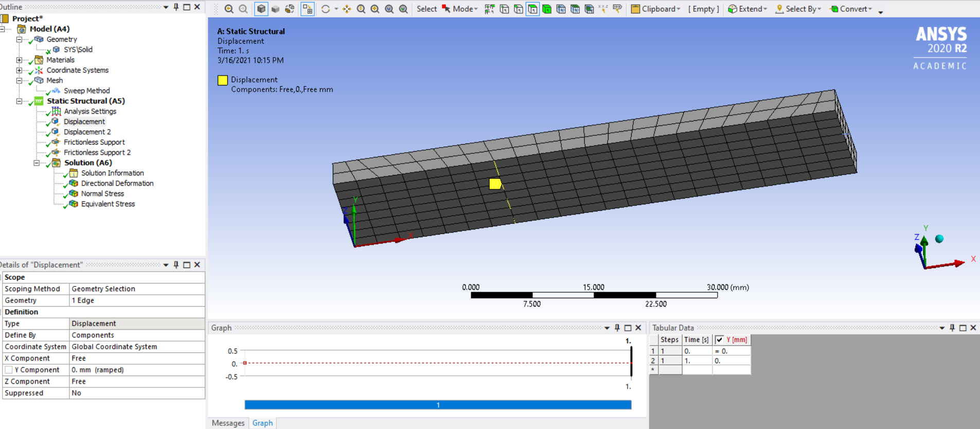 nn
nn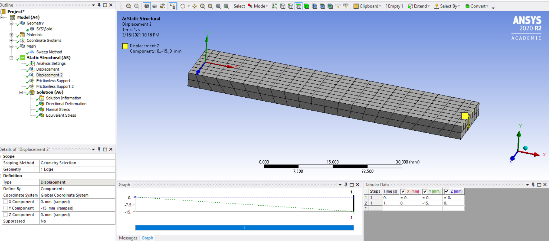 nHere are the results I obtained which are different and there is a warning ( the deformation is large compared....)nn
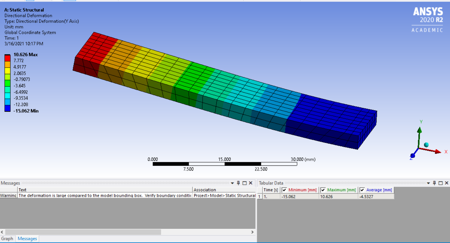 n
n n
n nThank you in advance.nn
April 4, 2021 at 7:56 pm
nThank you in advance.nn
April 4, 2021 at 7:56 pmMshrest2
SubscriberHi,nIn the model with solid rods used for bearing and pusher, how was the contact defined between the rod and the beam? nViewing 3 reply threads- The topic ‘3 point bending test on a beam’ is closed to new replies.
Innovation Space Trending discussions
 Top Contributors
-
peteroznewman
 5899
5899 -
scabo
 1906
1906 -
Dennis Chen
 1420
1420 -
javat33489
 1306
1306 -
Shyam Prasad V Atri
1021
Top Rated Tags
© 2026 Copyright ANSYS, Inc. All rights reserved.
Ansys does not support the usage of unauthorized Ansys software. Please visit www.ansys.com to obtain an official distribution.
-


The Ansys Learning Forum is a public forum. You are prohibited from providing (i) information that is confidential to You, your employer, or any third party, (ii) Personal Data or individually identifiable health information, (iii) any information that is U.S. Government Classified, Controlled Unclassified Information, International Traffic in Arms Regulators (ITAR) or Export Administration Regulators (EAR) controlled or otherwise have been determined by the United States Government or by a foreign government to require protection against unauthorized disclosure for reasons of national security, or (iv) topics or information restricted by the People's Republic of China data protection and privacy laws.
