TAGGED: 2d-axisymmetric, integration-point
-
-
April 5, 2024 at 11:08 am
Puhia Qalaj
SubscriberHi,
I'm contacting you because I have a few questions concerning the 2D axisymmetric simulations I'm currently running.
Currently, I'm generating meshes made up of quadrilaterals and in my simulation results, I notice that the type of element used is PLANE183. I'd like to find out more about these elements, in particular how many integrations points they use and whether they are configured in "reduced" or "full" mode.
I'm also wondering if it's possible to change these settings so that the elements use a "full" number of integration points. I'd like to know if there are any methods or options for doing this.
Finally, I'd also like to know if it's possible to determine the type of element used before even starting the simulation. At the moment, I only know one way, which is to check in the solver output after running the simulation.
Thank you in advance for your help !
Puhia
-
April 8, 2024 at 11:01 am
Stella Peloni
Ansys EmployeeHello,
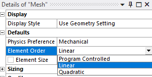
In this link, you will find all the details about the element PLANE183. This element is a higher order 2D element (8-node or 6-node), which can be used as an axisymmetric element. On the other hand, if you wish for a linear element, the PLANE182 can be a choise for axisymmetric simulations. In this link, you can get all the information for this element. Additionally, in order to specify through Mechanical, what type of element you wish to choose (linear or higher order), you could change the Element order option in the Mesh Details window (see picture).
Finally, if you want to visualize the type of elements are used prior solving the analysis, you can click on the Environment in the ribbon and then Write input file. In that way, you will extract the ds.dat file, in which all the nodes, and elements are stated.
For example, in the picture presented below, you can see that the element type used is PLANE183.
Have a great day!
Kind Regards,
Stella
-
- The topic ‘2D axisymmetric – Number of integration point in the element’ is closed to new replies.


-
3427
-
1057
-
1051
-
896
-
887

© 2025 Copyright ANSYS, Inc. All rights reserved.


