Ansys Learning Forum › Forums › Discuss Simulation › General Mechanical › How joint force is distributed among fem nodes in transient simulation. › Reply To: How joint force is distributed among fem nodes in transient simulation.
 josegegas
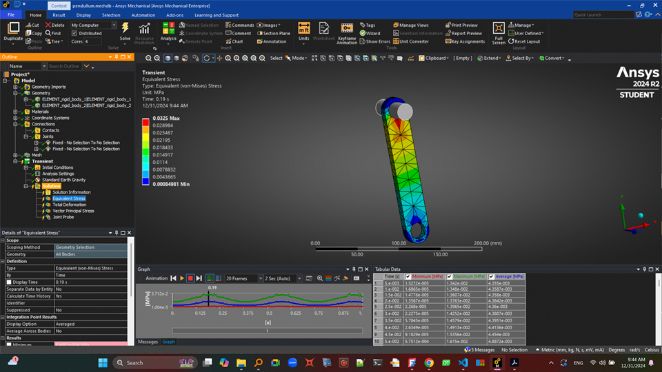
Here is an image. There are two joints: A fixed joint grounds the pin, and a revolute joint connects the pin and the pendulum (although, I do not know why; Ansys shows the second joint label as "fixed", but it is in fact a revolute). I set Earth's gravity pointing to global -Y. The pendulum is initially at the horizontal position, aligned with global X. The hinge axis is parallel to global Z, so the pendulum swings along the X-Y plane. When the pendulum swings, the revolute joint sees a reaction force. I have verified the value of this force by using another software to perform the same simulation and coparing the forces with those computed by Ansys. Reaction forces are correct. The bearing face is the cylindrical inner face of the pendulum hole, around which it pivots. I have removed the contacts Ansys adds bu default. I use solid tetrahedron elements for the mesh. I want to see the stresses in the pendulum resulting from the swinging. For this, Ansys should distribute the revoute joint force among the nodes that belong to the bearing face, and of course include the inertial forces resulting from the swinging in the fem simulation. But the thing is that the result stress distribution does not make sense. In the image above you can see von-Mises stress when the pendulum is near its vertical position (when the joint force is maximun and points to global +Y). You can see stress is concentrated at the bottom of the hole, which does not make sense: it must be at the top and in the sides instead. I believe this is because Ansys is distributing the joint force among the nodes in the bottom half of the hole instead of in the top, but Im not sure about this. So I would like to know how Ansys distributes rigid joint loads into the fem nodes, and If I have any control over how loads are distributed?
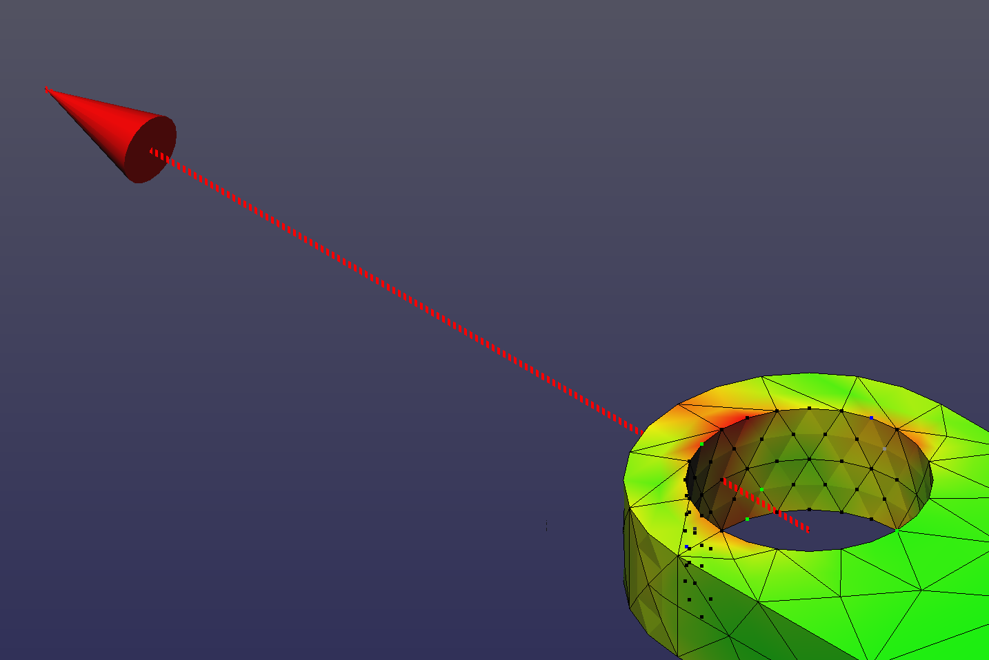
Here is a picture of what I am convinced is the correct stress distribution, simulated using another software.The red arrow is the joint force when the pendulum is vertical (half of its oscillation). The force computed by Ansys is correct: it is the same as the red force vector shown above and calculated with the other program. You can see that here the stress distribution is different than in Ansys results, and this stress distribution makes sense considering the force that the pin puts on the bearing face of the pendulum. In this image you can also see highlited the nodes among which the joint force (red vector) is distributed. These are only half of the nodes in the bearing face: in real world the pin would exert force only among these nodes. So given that Ansys is computing the correct joint force I think the problem is that it may not be distributing this force correctly among the nodes? I used exactly the same geometry for both simulations, same CAD, same density, same Young modulus and Poison's ratio, and verified mass and inertia matrix are good in both cases. Here is a video for reference. The first is Ansys and the second is the other software:
https://www.youtube.com/watch?v=8q90GKWCilQ


