Ansys Learning Forum › Forums › Discuss Simulation › General Mechanical › meshing a semi-elliptical crack › Reply To: meshing a semi-elliptical crack
October 25, 2023 at 9:49 pm
Ansys Employee
Hi,
- You can access the guide online here: https://ansyshelp.ansys.com/account/secured?returnurl=/Views/Secured/corp/v232/en/ans_frac/ans_frac.html
- If you are only evaluating the fracture parameters, then a hex mesh will be more efficient; it will produce good results using a lower number of elements than a tet mesh. If you are performing crack growth, you will need to use a tet mesh instead.
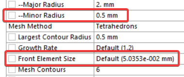
- We can take the crack length, ‘a’, to be the user-defined minor radius value of the semi-ellipse. The Largest Contour Radius should be set to this value. As a check, you can experiment with going above or below that value, comparing the results from each run. You’ll find that some variation in the largest contour radius parameter is permissible as the respective fracture parameter results should be comparable. Just an additional note: when Mechanical calculates the default Front Element Size (when Mesh Method = Tetrahedrons) you will notice that it produces a value that is roughly equal to the minor radius divided by 10. This indicates that acceptable mesh resolution for calculating fracture parameters is driven by the minor radius value. Some users use a/8, a/10, and in some cases a/20. This will depend on your geometry, loading conditions, and stress field around the crack area. Before doing a large run, it’s a good idea to test these parameters so that you can ultimately set up an efficient run that also produces acceptable results.


