Ansys Learning Forum › Forums › Discuss Simulation › Electronics › How to apply the current along the -z direction? › Reply To: How to apply the current along the -z direction?
Hi Zhongchao,
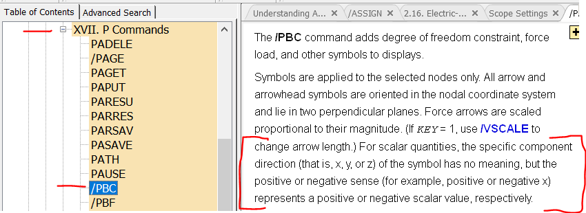
Actually, I'm quite certain your APDL code will apply the current in a direction normal to the surface at z=8.33E-3 (as you intend it to). My guess is that your concern stems from the appearance of the symbol representing your applied AMPS load (e.g., the image created by /PBC,AMPS,,1 followed by EPLOT). Current is a scalar, not a vector. In MAPDL, symbols representing applied scalar loads are always displayed pointing in the x direction. The /PBC documentation alludes to this, though the description is admittedly pretty vague:
Coupling the VOLT DOF on the surface as you have, the calculated voltage of all the nodes on that surface will have the same value => there will be no voltage gradient tangent to that surface => current will only be allowed to flow perpindicular to that surface.
One thing that may be a problem though (I'm not sure) is the last two lines of your code. After coupling VOLT, one typically applies all of the current to be applied at the surface to the single "master" (lowest numbered) node of the coupled degree of freedom set. I'm not sure applying current to the other non-master nodes (as you have done) will be recognized by MAPDL. You may end up having only I/TotalNodes current applied to the surface. The single command I would use in place of your last two commands is:
F,ndnext(0),AMPS,I ! APPLY ALL CURRENT ON THE NEXT HIGHEST NUMBERED NODE ABOVE ZERO
I'm confident that will work correctly.
Kind regards,
Bill


