Ansys Learning Forum › Forums › Discuss Simulation › General Mechanical › Capacitance analysis of parallel plate capacitors in MAPDL › Reply To: Capacitance analysis of parallel plate capacitors in MAPDL
Hi Yuuhi,
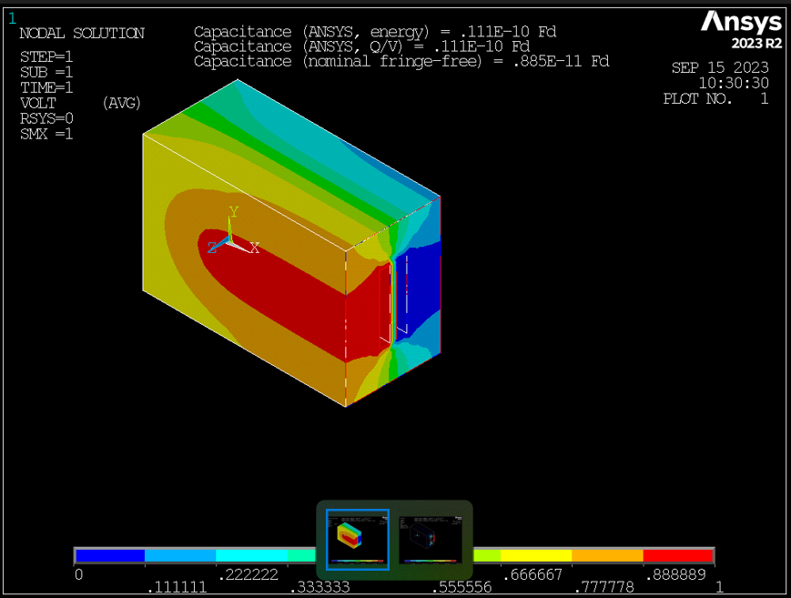
I'm sorry I don't quite understand your question. The input file creates annotated images such as the one below. The first two lines of annotation report the MAPDL-calulated capacitance including fringing deduced from results in two different ways. The third line reports the analytical fringe-free value, which is, as we expect, smaller. 
Maybe I'm missing something, but I don't see how you are using loop variable "i" to vary the size or separation of the plates. Are you asking how to vary the geometry in a do loop to investigate the effect of geometry on fringing and capacitance?
Or are you asking for an analytical expression that accounts for field fringing so that you can validate the calculated value from the finite element model? You might have to search the internet for that. I don't think that this article is exactly what you want, but it might help give you an idea what kind of articles you might find if you look further:
(PDF) Effect of Fringing Fields on the Capacitance of Circular Microstrip Disk (researchgate.net)
Kind regards,
Bill


