Ansys Learning Forum › Forums › Discuss Simulation › Photonics › How is free space treated in FDTD? Where to put monitors? › Reply To: How is free space treated in FDTD? Where to put monitors?
March 24, 2022 at 8:31 pm
 Guilin Sun
Ansys Employee
"Isn't there always a material interface in the simulation as long as you have materials / structures? Could you provide an example of what you meant by this?"
not true. When the substrate is truncated by PML, except the top air/material interface, there is no other interface.
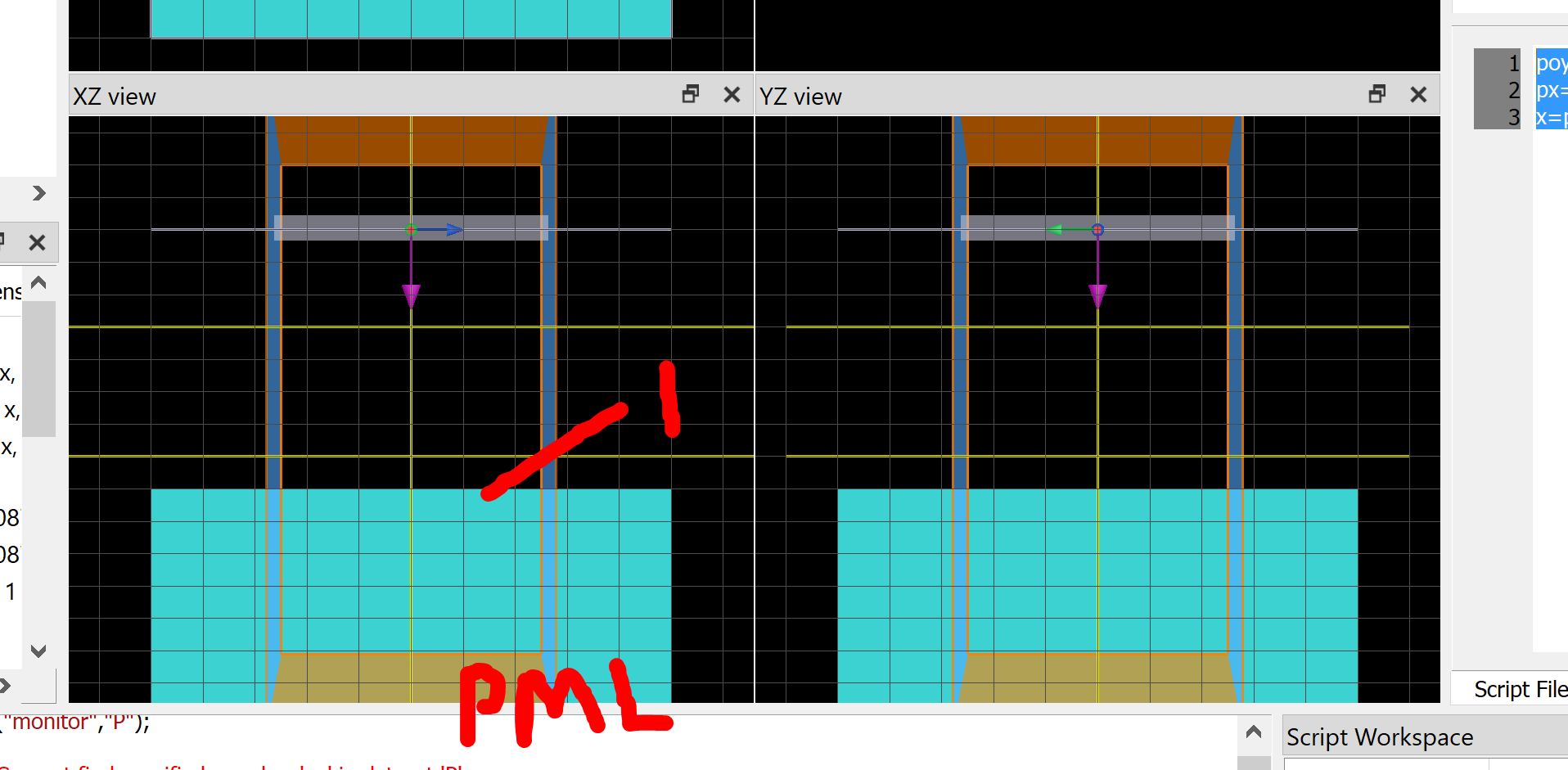
Since it is a cavity, and you plot transmission and reflection, it is normal to have different peaks and valleys. PLease place a monitor behind the source and add R+T to check if it is smaller than or equal to 1 within simulation errors.
When the monitor is in between the source and the front surface, you will need to add or substract 1 from the monitor transmission. Please refer this Tips for accurately measuring reflection in an FDTD simulation
not true. When the substrate is truncated by PML, except the top air/material interface, there is no other interface.
Since it is a cavity, and you plot transmission and reflection, it is normal to have different peaks and valleys. PLease place a monitor behind the source and add R+T to check if it is smaller than or equal to 1 within simulation errors.
When the monitor is in between the source and the front surface, you will need to add or substract 1 from the monitor transmission. Please refer this Tips for accurately measuring reflection in an FDTD simulation
