
-
-
March 30, 2021 at 4:31 pm
Aslinn
SubscriberHi,
I am doing a mesh sensitivity study on a simply supported deep beam with one point load in the mid span. The deep beam is 2m long with a cross section of 1m x 0.1m. I am using element SHELL181, and trying to increase element numbers until I see convergence, which I take as a sign of sufficient mesh density. I used displacement as the criteria since I think displacement is not affected by singularities or stress concentrations like stresses do. However, I have used 16958 elements but the vertical displacements are still changing. I have attached my recorded results below. Could someone help me to understand why is this and how can I know I which mesh density is sufficient?
Thank you!
March 30, 2021 at 5:28 pmpeteroznewman
SubscriberArraynInstead of Element numbers, plot element edge length at the area of interest. That way, you will get a series of points trending toward zero.nIf you extrapolate the last two points to zero element edge length, that is the true solution for displacement.nMarch 30, 2021 at 5:42 pmSubscriber@Aslinn Instead of Element numbers, plot element edge length at the area of interest. That way, you will get a series of points trending toward zero.If you extrapolate the last two points to zero element edge length, that is the "true" solution for displacement./forum/discussion/comment/113335#Comment_113335
Hi Peter, thank you for your reply. May I ask where can I find element edge length? Is it the same thing as element size under the Mesh setting?nMarch 30, 2021 at 6:37 pmSubscribernIt depends on how you were refining the mesh. Did you use only global size controls? Then that is the element size to use.n However, most analysts use a local mesh size control and pick the faces where the high stress occurs to have a smaller element size than the global size. Another method is a size control on the body, but use a coordinate system and a sphere of influence to get smaller elements below the surface. In either of those cases, it is the element size used in those local controls.nYou can also just measure the distance between nodes on the mesh at the location where you are recording the maximum stress.nMarch 30, 2021 at 6:57 pmSubscriber@peteroznewmann@Aslinn It depends on how you were refining the mesh. Did you use only global size controls? Then that is the element size to use. However, most analysts use a local mesh size control and pick the faces where the high stress occurs to have a smaller element size than the global size. Another method is a size control on the body, but use a coordinate system and a sphere of influence to get smaller elements below the surface. In either of those cases, it is the element size used in those local controls.You can also just measure the distance between nodes on the mesh at the location where you are recording the maximum stress./forum/discussion/comment/113345#Comment_113345
Thank you. In this case I just used the global control. I plot the displacement VS element size. So essentially we are using the slope of this curve to get the 'true' value, right? In this sense, does it mean we will never converge by increasing the mesh density, because FEM as a numerical method can only approach the answer, not reach it? Then, how do we know what is a 'good enough' mesh size to use?n n
March 30, 2021 at 7:57 pmSubscribernIt means you have a singularity in the model. Applying a force to a single node in a solid element model is an example of a singularity. The smaller the elements get, the higher the displacement. The proper way to model that is to spread the load over an area of nodes. That is more realistic of the conditions of physical hardware. If you do that, you will find the displacement quickly converges and the slope goes almost flat on the graph of displacement vs element size.nMarch 30, 2021 at 8:26 pmSubscriber
n
March 30, 2021 at 7:57 pmSubscribernIt means you have a singularity in the model. Applying a force to a single node in a solid element model is an example of a singularity. The smaller the elements get, the higher the displacement. The proper way to model that is to spread the load over an area of nodes. That is more realistic of the conditions of physical hardware. If you do that, you will find the displacement quickly converges and the slope goes almost flat on the graph of displacement vs element size.nMarch 30, 2021 at 8:26 pmSubscriber@Aslinn It means you have a singularity in the model. Applying a force to a single node in a solid element model is an example of a singularity. The smaller the elements get, the higher the displacement. The proper way to model that is to spread the load over an area of nodes. That is more realistic of the conditions of physical hardware. If you do that, you will find the displacement quickly converges and the slope goes almost flat on the graph of displacement vs element size./forum/discussion/comment/113354#Comment_113354
Yes I do have a singularity in the model. It is an assignment and that is the requirement...so can't change it. The point I choose to moniter is very far away from the singularity though, is it still affected? I thought according St. Venant’s Principle, the point far away from the singulartiy should not be affected?nMarch 30, 2021 at 8:33 pmSubscribernYes, points far from the load will converge quickly.nHow are you monitoring the deformation of that point which is far from the applied load?nMarch 30, 2021 at 10:21 pmSubscriber@Aslinn Yes, points far from the load will converge quickly.How are you monitoring the deformation of that point which is far from the applied load?/forum/discussion/comment/113360#Comment_113360
The load is applied at the top of the beam, and the point (the red cross) I have is at the bottom, as shown below. I recorded the vertical displacement of this point when changing the mesh density. That displacement is what I used to plot the graphs in previous posts.nn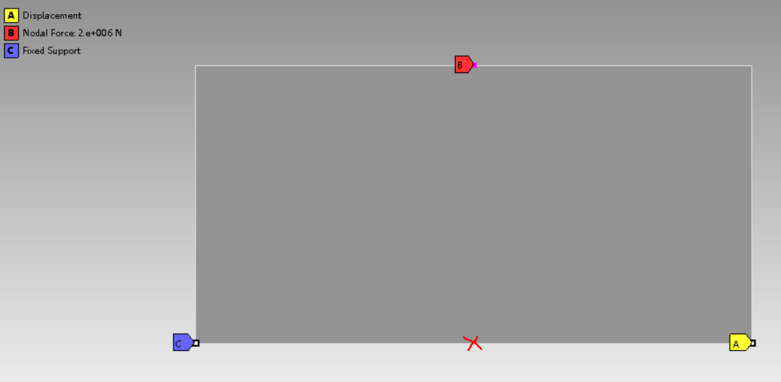 n
Viewing 8 reply threads
n
Viewing 8 reply threads- The topic ‘Mesh sensitivity’ is closed to new replies.
Innovation Space Trending discussions
 Top Contributors
-
peteroznewman
 5844
5844 -
scabo
 1906
1906 -
Dennis Chen
 1420
1420 -
javat33489
 1305
1305 -
Shyam Prasad V Atri
1021
Top Rated Tags
© 2026 Copyright ANSYS, Inc. All rights reserved.
Ansys does not support the usage of unauthorized Ansys software. Please visit www.ansys.com to obtain an official distribution.
-
Ansys Assistant will be unavailable on the Learning Forum starting January 30. An upgraded version is coming soon. We apologize for any inconvenience and appreciate your patience. Stay tuned for updates.


