Ansys Assistant will be unavailable on the Learning Forum starting January 30. An upgraded version is coming soon. We apologize for any inconvenience and appreciate your patience. Stay tuned for updates.
Preprocessing

Preprocessing

Topics related to geometry, meshing, and CAD.

any body know about nTopology software and how we can import geometry from nTop to ansys workbench?

    • Mansoureh
      Subscriber
      hello dear all,nAny of you have experience with nTopology software? I am stuck in how can i import my geometry or my mesh into ansys workbench?nit gives us a mesh file in format .cdb, .k, .inp which are for mechanical apdl, ls-Dyna, and abaqus respectively. but when I am trying to use these file for a mechanical workbench and import my mesh into ansys with the file format of cdb or inp file, the geometry is not changeable and I can not define any boundary condition or select any surface, it seems the whole body is one without any surface to point or line.nIf anybody can guide me?nthanksn
    • Sean Harvey
      Ansys Employee
      Hello Array,
      The workflow you have will not give you geometry you can change. For cdb file import, if nTopology wrote out APDL components to identify the faces, then when the geometry is synthesized in Mechanical it could use those to give selectable faces/named selections.
      Now I have seen students export the stl (facets), then take that into SpaceClaim. Then in the tools tab, they can skin surfaces, and end up reverse engineering to get a solid, which could then be modified. There is also a facets tab that has features to do this. This process can be easy or more time consuming depending on the complexity of your geometry. You can then right mouse button on the body in the tree and create a solid.
      If you need more information on this process, let us know and we can try and provide details, but first I would see if you can bring in the stl and get access to the tools and facets tab.
      Once you have it in SpaceClaim, you take it into Mechanical, etc.

      Hope this helps. Thank you
      Sean
    • Sean Harvey
      Ansys Employee
      .

      Hello @mansoureh,

      I forgot to mention that if in the external model to mechanical workflow, right mouse button the link between the systems, pick properties, then select the downstream model cell (in this case E3) you will have properties you can change. Make sure create geometry is picked (which you most likely already have) but you can change the tolerance angle and Mechanical will subdivide the face into smaller faces depending on the angle between the normals. There is also a vertex insertion angle tolerance. Please try those too and see if it helps! See image below.


      Regards,

      Sean

      .
    • ramgopisetti
      Subscriber
      .

      hi Mansoureh , the answer to your question is simple, ntopology exports the body into neutral file files follow the link below how to export.

      as sharvey had mention the procedure to recreat the geomentry in the above post, you can also able to work with mesh files.

      comment down for futher help

      happy generative designing

      cheers, Ram

      .
    • Mansoureh
      Subscriber
      .

      Dear @sharvey 

      Thank you so much for your answer. and sorry for delay from my side. I am involving in my design, finally I could bring a stl file from an initial structure to Ansys space claim. if i bring STL file, because of complexity of my structure, there is some problem like mesh is inter-secting and after solving that another problems appear, you can see in the below image

      I saw some tutorial but they could not help me for solving my problem. do you have any other tutorial or suggestion, i am beginner in space claim.

      and could you please tell me, can I edit any stl file in space claim? even more complex ? unfortunately in papers and article, any body did not mention how is the process for converting stl file to a suitable format for FE analysis.

      and how about Hypermesh? can I use that for edit stl file or obj? because Hypermesh can give us cmdb file for workbench (but i did not know after that geometry is editable or not to add solid body up and bottom of my structure). I did not know about hypermesh ability.

      As you mention me in another your post, I tried to bring my mesh from nTop to ansys workbench, but the problem is that I need to define solid body/surface up and bottom of this structure for compression test, but after bringing the mesh from nTop it is impossible to define any other body.

      another question: I could not edit the mesh in workbench anymore ? right? because I need to do mesh sensitivity for my structures, do you have any suggestion about that?

      and how about APDL, if i want to use that?

      I am so confused between which process can i use, this is 3 weeks i am searching websites and softwares, reading comment, asking from some authors of papers(no body answer), i was so happy, you answer and help me. i hope i can solve my problem and my work goes on with your help. thank you so much

      .
    • Mansoureh
      Subscriber
      Dear @ramgopisetti
      I saw all of them, but for my structure because of complexity, it is impossible to do that process to quadrate the mesh and gives me manifold error. i tried to export my triangle mesh in format cdb, inp, k or stl, obj file. i am searching to find the best way for preparing my file for ansys analysis and to be editable for adding solid body/ surface up and bottom of my structure for compression test.
      do you have any suggestion in this area that can be helpful for me?
      thank you so much
    • peteroznewman
      Subscriber
      Array
      I read the link for export formats that Array provided. I recommend you follow the directions in that link to convert to a CAD format and not export the mesh. I see that nTopology can export a Parasolid file. That is your best option. Please let us know if that works out better for you.
    • Mansoureh
      Subscriber
      .

      Dear @peteroznewman


      Thank you for your answer.

      Indeed, there is some problem here. I mention them one by one maybe you can help me to find a solution. I tried to follow the directions in that link that ramgopisetti mentioned.

      I wanted to model so complex structure like the Voronoi lattice, they are irregular beam strut that they are connected to each other. sometimes if they are full of struts with gradient thickness that it is so difficult to export CAD files from them. In nTop there is some process to do that. at first, we should define tetrahedron mesh and next convert it to quadrate and then export CAD file, but for my structures due to the connections and complexity, converting to quad is impossible and give me some errors. it means I can not have a CAD file(STEP or Parasolid) from my lattice.

      I tried to export a CAD file for a simple Voronoi structure. it is so simple with big porosity and few beam struts. after that, I import my step file to ansys, there are so many small surfaces that I should merge all of them, and sometimes I face an error that they can not be one surface. ( think

      I tried to mesh my imported lattice with these small surfaces, but if you see the images. the mesh is not good because of the existing so many separated surfaces.

      You know, the main problem is that:

      1. nTop don't give me a CAD file for so complex structures and

      2. if by any chance (that I think it is impossible) I can export that as CAD file, for my complex lattice maybe there are a million surfaces which merging them is so time-consuming and maybe impossible. so I should try to find another way to bring my lattice to ansys.

      In nTop 's slack, some experts said we should export tri surface mesh and do the rest in ansys. but after doing that, nTop give me .cdb file which is not editable at all. and my lattice is hollow, not solid.

      dear @peteroznewman can you help me to find a way to solve my problem?

      May i ask you to take a look at this like, in nTop website, maybe you can guide me which way I can use. I cant understand exactly what should I do for exporting data for ansys?

      https://support.ntopology.com/hc/en-us/articles/360039792513-What-types-of-FE-data-can-I-export-

      I greatly appreciate it.

      I attached my image here:


      .
    • peteroznewman
      Subscriber
      Array
      Please start at the beginning. What is your goal? What are you trying to accomplish, at a high level? What are your requirements?
      How does nTop claim to support this goal?
      What other software might be able to support your goal?
      Did you look at this: https://www.rhino3d.com/6/new/grasshopper/
      Did you consider creating the geometry in SpaceClaim?
    • Mansoureh
      Subscriber
      .

      Dear @peteroznewman

      My goal is to model some complex structures for bone application (I put some images below for showing to you what is my mean, these are from some papers that I found) . These complex structures can have different thicknesses, different pore size, and different unit cells type in gradient in for example z direction( you can see in below images).

      nTop and grasshopper completely cover this requirement for designing and they have really perfect options for designing suitable lattice for bone application and 3d printing But I chose nTop because is free for students, and no need license.

      The next step after designing , is doing a compression test in both experiments and FE analysis to choose the best one from a mechanical point of view. and then comparing FE result with experiments. Now there are two aspects:

      1. there is no problem with 3d printing because nTop give me STL file.
      2. But for FE analysis and doing compression test in ANSYS, as you know we need a Step or Parasolid file. For doing compression test in ansys , I need to define two solid surfaces/bodies on the top and bottom of my structures. After importing my lattice to ansys i should define this solids and prepare them for compression.

      This is my goal.

      How does nTop claim to support this goal?

      Besides designing options in nTop, it has some option to export Step, Parasolid, STL and some option for exporting FE mesh as " cdb " (APDL file) , "inp "(ABAQUS file) , "k" (Ls_Dyna) files. (https://support.ntopology.com/hc/en-us/articles/360039792513)

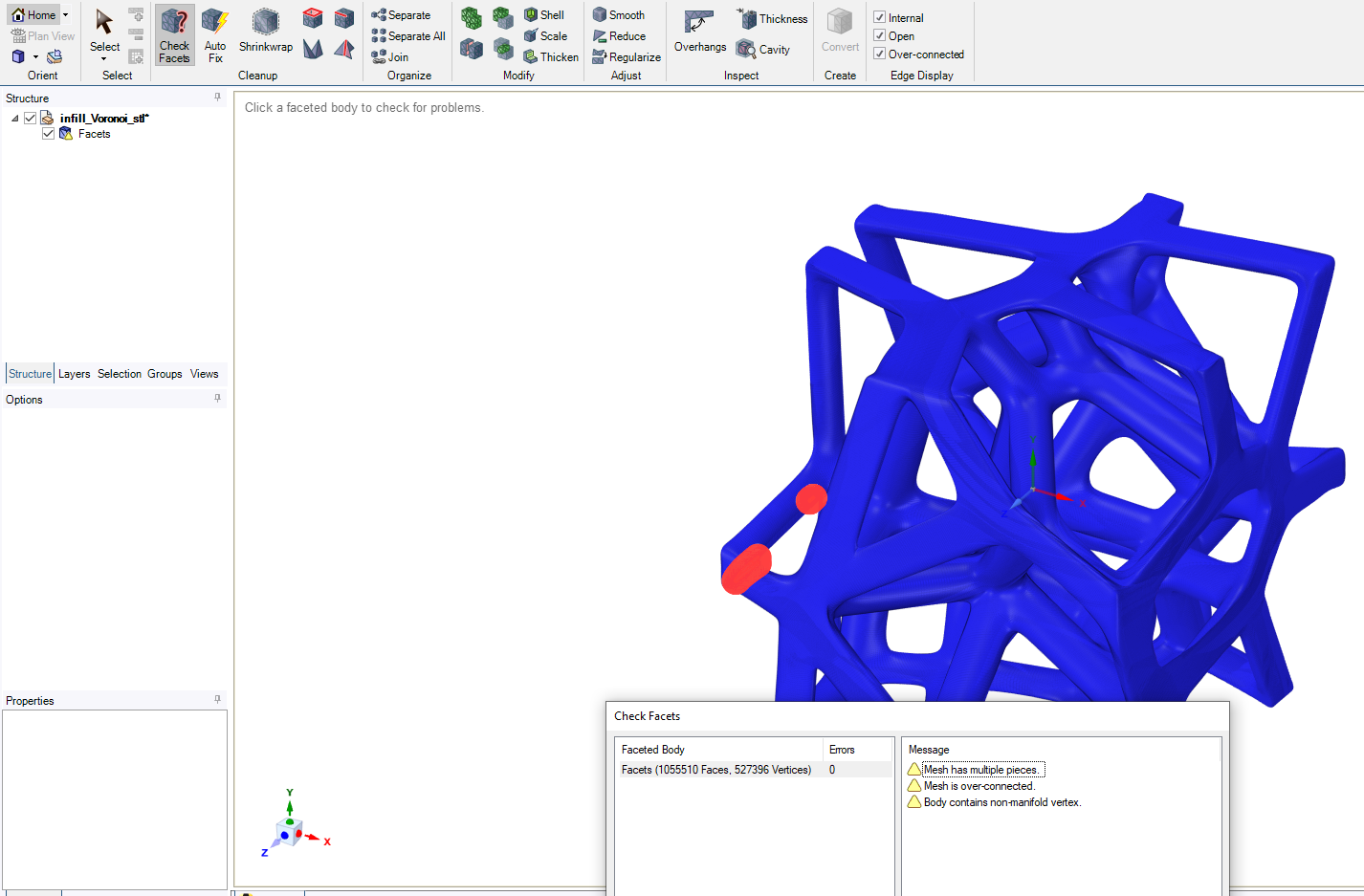
      Obtaining step or parasolid file for complex structure is so difficult as they mentioned in their website as well. i think this option support simple structures like optimized structures or less complexity. For exporting so complex structures it gives you an manifold error. So just left two other option, exporting STL file or FE mesh.

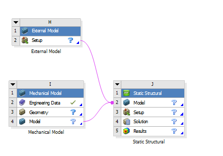
      They suggest to export FE mesh for using in ansys, I tried that. And I saw that after importing FE mexh as cdb file, I could not define any other geometry (i mean solid body / surface to do compression test)

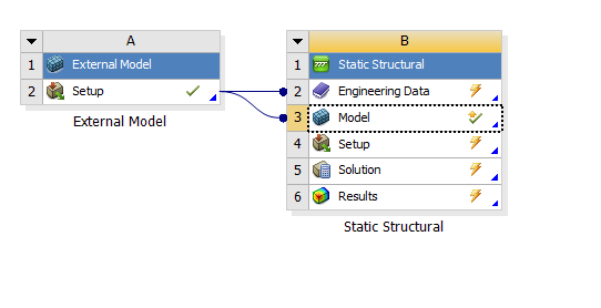
      For importing cdb mesh file to ANSYS, I used "external model" option, and if i connect it to "static structural" , I could not edit any thing to add some solid body or etc.

      What other software might be able to support your goal?

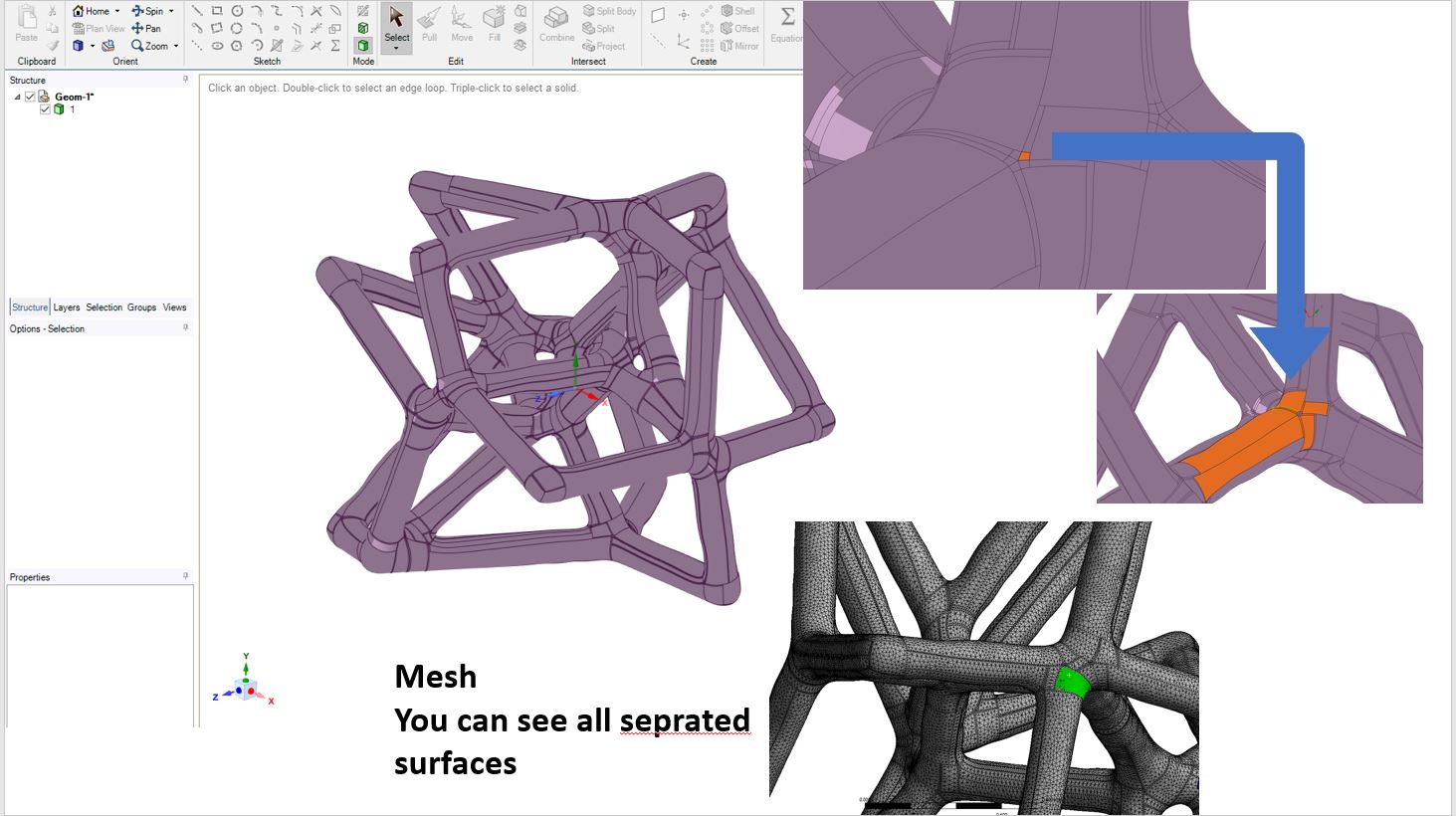
      actually I think it should be an option to mesh stl file and then import that mesh to ANSYS, Am I right?

      because i saw in some papers, they used grasshopper for designing but they did not mention at all about the process to prepare the model for FE analysis and they did FE analysis for their structures. some body use nxNastran and femap simultaneously , some body use meshlab and somebody introduce Rhino for that purpose. But I am not familiar with these software and which one can exactly do my goal.

      i am not sure but I think one way is preparing stl file ,next try to mesh stl file and then bring mesh and nodes into ansys. what is your opinion about that? and if yes, what is the best software?


      Did you look at this: I saw grasshopper but because it needs a license, I prefer to start with nTop. i dont know grasshopper can give us step file foe complex structures or it is needed to use other software as i mentioned above.

      Did you consider creating the geometry in SpaceClaim?

      actually I dont know , i just use spaclaim to try . i dont know space claim can help me or not. i am not familiar with space claim.

      can we work on stl file in space claim to prepare that for static or dynamic anlsysis?


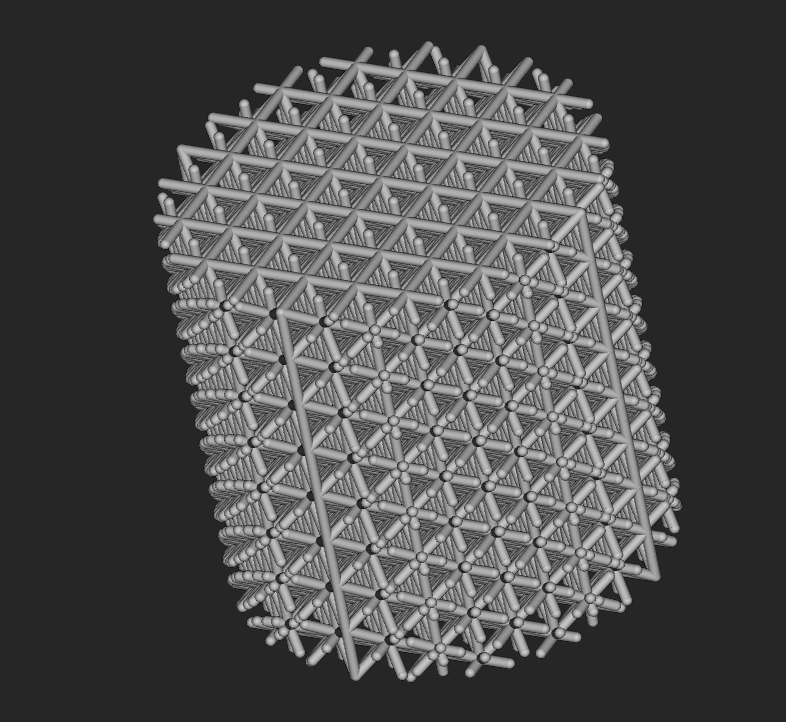
      images that i mentioned before:

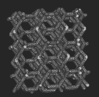
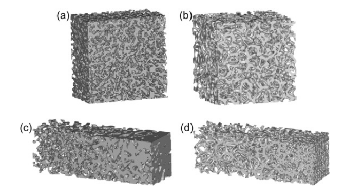
      1. this is one type of my desired structures, that i can design with nTop.

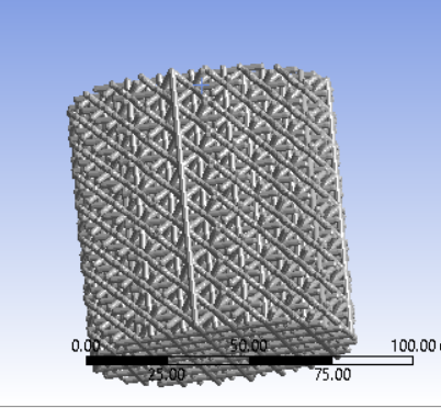
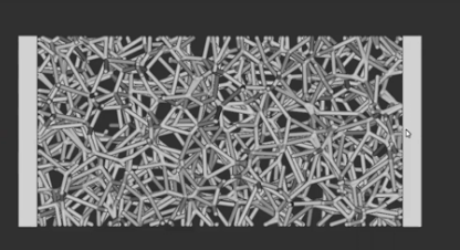
      2 another image in one prepare ( used grasshopper and Abaqus , the did not mention about how they bring model to Abaqus)

      scaffolds and EF analysis:

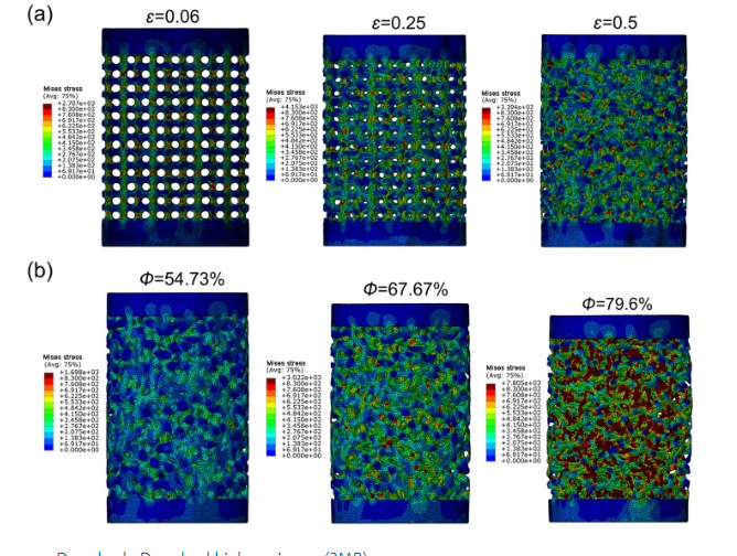
      i want to do sth like this with ANSYS.

      Thank you so much, for your help. and your time, is it so valuable for me.


      .
    • ramgopisetti
      Subscriber
      Hi Array , sorry for the delay, ok it’s clear to me that you want to model vornoi structures, this is easy if you employ algorithmic design via grasshopper using rhino.
      Based on the image what I can see is that lots of surfaces which are generated because the engine behind ntopology was bsplines and implicit modelling , to simply your process, you need to adapt to ANSYS discovery to import the geometry as obj and setup the simulation and transfer it to workbench for additional and detail study. By this you can screen the issues and reduce the geometry preparation.
      you have to export the body from ntopology as obj and you can import it into discovery product.
      comment down for further help
      cheers ram
    • Mansoureh
      Subscriber
      Hello everybody, thanks to all for your responses and helps.
      I have solved my problem and successfully I could bring my design into Ansys. I want to leave comments here maybe for somebody to be useful.
      In nTop software, there is some option you can export your geometry. you can create the surface mesh for exporting the geometry as an STL file easily and then if you want to export mesh into Ansys or Abaqus, you should created volume mesh and then create your FE model, Boundary conditions and then export all the meshes for geometry and all the mesh or nodes or edge for boundary condition as well.
      I understand, if you export boundary as mesh, in Ansys they go into named selection but you can not create a remote point for them to apply BC like displacement of force, But if you export the nodes, you have named selection for them in ansys and then you can create a remote point for them and then apply your boundary conditions.
      Just about the connection, I am in doubt and I should test the conditions. if I understand any important point, I will explain here in the future.

    • dayakarthic
      Subscriber
      .

      Mansoureh

      I want to perform similar kind of analysis for my research work. I created a lattice in ntopology and exported mesh from implicit body as stl file to Ansys workbench. But in Ansys I could not select the nodes or do mesh. I also want to perform compression test. Could you help me please?


      .
    • Mansoureh
      Subscriber
      .

      dayakarthic


      You have to export the mesh in the format of .inp and then import it to ansys to do the rest work. you have to define your plate in ansys in mechanical model and then connect them to your main block to do the rest of the analysis. STL format does not work in ansys for our case.

      .
    • dayakarthic
      Subscriber
      .

      Mansoureh

      Thankyou so much for helping me. My lattice looks like this. I could move my STL file to ansys but I can't generate mesh. It is showing poor quality or incorrect input error. It seems I need to do FE Volume mesh to export mesh as .inp file as you told which is taking hours to complete sometimes ntopology closes automatically in the process due to overload in our system. I also want to add that I cannot select faces in Ansys because my component is fully latticed. I do not know how to add top and bottom surface for analysis. Sould I need to do that in Ntopology or Ansys. My project needed to be completed only using ntopology and Ansys. Once again Thankyou

      .
    • Mansoureh
      Subscriber
      .

      @dayakarthic

      I would suggest you to change the dimension of your lattice bigger than that, use a big unit cell and thicken the struts, normally it takes time to mesh this type of structure but you should try several methods to mesh for example "mesh implicit body by voxel grade" tor " mesh from implicit body "and play with the parameter and the use remesh surface to reach to the final mesh. you should play with parameters to understand which method is better to create a mesh and which one gives you the best mesh, i think this ability just can reach by practicing.

      If your structure is so heavy it will be close, try to optimize your lattice at first then try to mesh it.

      you should create the face from your lattice in ntop. if you look carefully onto the top and bottom of status of your lattice, they do not have any surface, they are just like dots. Create your lattice bigger than your final dimension and then cut it into the desired size so you can have the surface on the top and bottom. you should extract the face with your mesh. try to watch some video to figure out how to do that

      you have to create the final plates for the compression test in ansys as i said before.

      .
    • dayakarthic
      Subscriber
      .

      Mansoureh

      Thankyou for your valuable suggestion. As you said I decreased my lattice size and successfully created FE Volume mesh. I also could add my .cdb file as external model in Ansys workbench. Finally I have one doubt, I am not able to attach plates top and bottom can you tell me how to do it exactly ( steps ). I tried analysis by selecting nodes but that did not work. So please tell me how to add the surface plates top and bottom to do the analysis. I have attached pictures of my new lattice and ansys workflow.

      .
    • Sean Harvey
      Ansys Employee
      .

      Hello dayakarthic

      If you create another mechanical model and setup the two plates as solids in SpaceClaim, then you connect as shown below. You then can use bonded contact to connect each plate to the lattice. In the bonded contact you can increase the pinball radius to capture more nodes of the latices if necessary. Imagine the plate is "glued" to the lattice. If you don't use enough "glue" you may just capture the tips of the lattice, so increasing pinball grabs more nodes like a thicker layer of glue. You can also go to each of the bodies of the plates in the geometry, pick on it and, and in the details, change their behavior to rigid to savecomputational time. You will then need to use remote force or displacement to control the plates, as regular displacements, forces won't work.

      Notice I don't have the engineering data shared as you do, not sure if you need that shared, but the below technique of sharing multiple modes with a single model cell is called model assembly.

      Try this technique and see how goes.


      Best Regards,

      Sean


      .
    • maikivlahinos
      Subscriber

      Hi Mansoureh,

      I quite randomly came across this post. Depending on the objective in Ansys, it's not a clear-cut answer. At the moment exporting an INP with the boundary conditions predefined in nTop is generally the best approach. Depending on the scenario you can also choose to export a surface mesh and use Ansys's Layer Tetrahedron Meshing Method. For going to Fluent, I generally recommended exporting a Surface MSH file with the boundary condition faces predefined in nTop as well.

      I realize this is a very late reply but I hope it is helpful.

      Thanks,
      Maiki

Viewing 18 reply threads
  • The topic ‘any body know about nTopology software and how we can import geometry from nTop to ansys workbench?’ is closed to new replies.
[bingo_chatbox]