
-
-
March 12, 2021 at 11:03 pm
monipmf
SubscriberHi,
March 15, 2021 at 1:17 ampeteroznewman
SubscribernSince the penetration is excessive, correct that by editing the contact Normal Stiffness. Change the Factor to be 10 or 100 from the default of 1.nTry putting 8 elements through the thickness of the thin plate. You must have at least 2 elements through the thickness of the thick plates.nYou may find it helpful to set the element to use the mixed u-P formulation. That is done with a Command object under the Solid in the Geometry folder to set Keyop(6)=1. There is a particular syntax to accomplish that:nkeyopt,matid,6,1nWhat material model are you using on the thin plate? You say it has a Poisson's Ratio of 0.48 which is nearly incompressible. You might benefit from changing the material model to a hyperelastic material if it is a rubber-like material.nMarch 16, 2021 at 10:54 amSubscriberHi Peter!Since the penetration is excessive, correct that by editing the contact Normal Stiffness. Change the Factor to be 10 or 100 from the default of 1.Try putting 8 elements through the thickness of the thin plate. You must have at least 2 elements through the thickness of the thick plates.nI updated the mesh with 3 elements through the thickness of the thin plate and minimum of 2 elements through the thickness of the thick components. Normal stiffness program controlled (=1) for a first try with the finer mesh. Other settings were: Augmented lagrange, nodal-projected normal from contact. (Normal lagrange takes even longer) Quadratic mesh for contact regions.nI let this calculating through out the night and this morning convergence was going well but after 8 hours it reached just 14% of the solution. This is a simplified model and the original would take too long to solve. n--------nYou may find it helpful to set the element to use the mixed u-P formulation. That is done with a Command object under the Solid in the Geometry folder to set Keyop(6)=1. There is a particular syntax to accomplish that:nkeyopt,matid,6,1nWhat material model are you using on the thin plate? You say it has a Poisson's Ratio of 0.48 which is nearly incompressible. You might benefit from changing the material model to a hyperelastic material if it is a rubber-like material.nnThese are great suggestions and I'll definitely try them. Could you give me a brief explanation about the mixed u-P formulation? Someone suggested me also the Gasket material. We used Gent's equation for young modulus estimation of iperelastic materials so we set up the material as isotropic and linear: E=3.6MPa, poisson = 0.48nFor now to get rid of the incompressible material (as I was stuck on that for too long), I calculated a theoretical stiffness of the thin layer (using the relation between F=kx and P=F/A) and then I used the k value as the stiffness of a spring (added springs where I had the thin layers) so that I have almost everything linear appart from a frictional contact which is set as predict for impact. The main goal of this analysis is to bolt together a sandwich of layers which has a gap due to deflection that should be closed.n-------nFrequently I have a continuous and slow convergence plot which stays for a long time (for example see image attached below):n Does it occure because of too high number of substeps?n---nLet me know if you find anything not accurate in my explanation and considerations. nThanks a lot for your reply!nMoninn
March 16, 2021 at 2:15 pmSubscriberUPDATE:nI ended up with springs but for the scope of the analysis I still have two thin components made of the elastic material which is making convergence harder to achieve but I need them to analise the gap status between parts. When I first added the elastic component the force convergence plot was:n
Does it occure because of too high number of substeps?n---nLet me know if you find anything not accurate in my explanation and considerations. nThanks a lot for your reply!nMoninn
March 16, 2021 at 2:15 pmSubscriberUPDATE:nI ended up with springs but for the scope of the analysis I still have two thin components made of the elastic material which is making convergence harder to achieve but I need them to analise the gap status between parts. When I first added the elastic component the force convergence plot was:n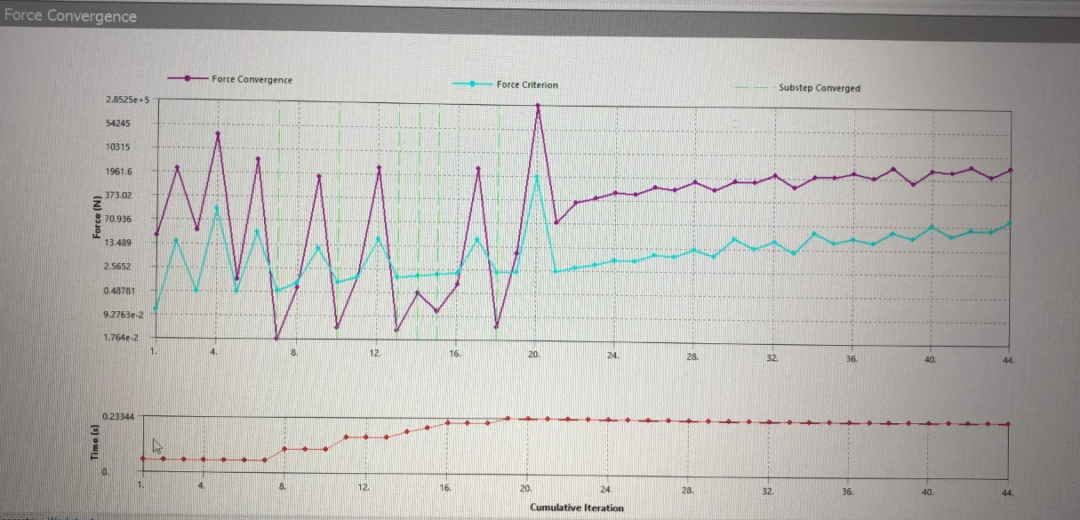 When I tried to solve the model again with adding more substeps plot didn't converge already from the beginning.nNot sure if I should use already an hyperelastic material instead of our 'isotropic incompressible'.n I'll keep working on it and it would be great to know your impressions about it.nnThanks again!n
March 16, 2021 at 5:17 pmSubscriberHi Moni nMixed u-P element formulation adds an independent pressure DOF to separate it from the element deformation. This makes it easier to converge the solution. You can read more about that in the ANSYS Help Element Technology Guide.nThere are more convergence criterion than just Force. There is also Displacement. If you change the plot, you will see that one of the other convergence criteria is having difficulty.nA gasket material model allows you to take experimentally measured Pressure-Closure data and use that directly on a single layer of elements. This is good if you want to get results on the two flanges that are compressing the gasket. But you seem to be more interested a wavy thin part and how much force is needed to squash it flat. nUnder Solution Information folder, you should type a 3 into the Newton-Raphson Residuals field so you can plot a contour of the location where the solver is struggling to converge.nMarch 18, 2021 at 7:14 amSubscriberHiArray,nthank you for your reply and all the info! But you seem to be more interested a wavy thin part and how much force is needed to squash it flat. Exactly.nKEYOPT has worked very well and plot is like this:n
When I tried to solve the model again with adding more substeps plot didn't converge already from the beginning.nNot sure if I should use already an hyperelastic material instead of our 'isotropic incompressible'.n I'll keep working on it and it would be great to know your impressions about it.nnThanks again!n
March 16, 2021 at 5:17 pmSubscriberHi Moni nMixed u-P element formulation adds an independent pressure DOF to separate it from the element deformation. This makes it easier to converge the solution. You can read more about that in the ANSYS Help Element Technology Guide.nThere are more convergence criterion than just Force. There is also Displacement. If you change the plot, you will see that one of the other convergence criteria is having difficulty.nA gasket material model allows you to take experimentally measured Pressure-Closure data and use that directly on a single layer of elements. This is good if you want to get results on the two flanges that are compressing the gasket. But you seem to be more interested a wavy thin part and how much force is needed to squash it flat. nUnder Solution Information folder, you should type a 3 into the Newton-Raphson Residuals field so you can plot a contour of the location where the solver is struggling to converge.nMarch 18, 2021 at 7:14 amSubscriberHiArray,nthank you for your reply and all the info! But you seem to be more interested a wavy thin part and how much force is needed to squash it flat. Exactly.nKEYOPT has worked very well and plot is like this:n Displacement has a very similar plot but I don't understand very well why it stops at 0.98nI have been reading about this error:n *** ERROR *** CP = 19421.922 TIME= 21:31:54n Solution not converged at time 0.982206054 (load step 1 substep 44). n Run terminated. nUnfortunately for this result I don't have any newton raphson residuals but I'll rerun it to see if I get the problem. If you have any suggestion it would be great.nnThank you,nMonin
March 18, 2021 at 10:58 amSubscriberHi Moni nOnce you see the location of the Maximum N-R Residual Force, improve the mesh at that location. Smaller elements may be required to help it converge.nYou also need to check penetration. If it is very small, you can help convergence by softening the contact. Edit the Normal Stiffness and use a Factor of 0.1.nAlso set the contact to update stiffness on every iteration.nMarch 24, 2021 at 2:31 pmSubscriberThank you for your reply and sorry for the long time for answering.nnI've been doing some smaller models to understand better the non convergence. I did a very simple model with thick bodies. Soft material is compressed by two bodies made of steel. As you said, with the hyperelastic material it converges. Instead, when I try to compress a polyethylene body elements get highly distorted. nMooney-Rivlin result (converged):n
Displacement has a very similar plot but I don't understand very well why it stops at 0.98nI have been reading about this error:n *** ERROR *** CP = 19421.922 TIME= 21:31:54n Solution not converged at time 0.982206054 (load step 1 substep 44). n Run terminated. nUnfortunately for this result I don't have any newton raphson residuals but I'll rerun it to see if I get the problem. If you have any suggestion it would be great.nnThank you,nMonin
March 18, 2021 at 10:58 amSubscriberHi Moni nOnce you see the location of the Maximum N-R Residual Force, improve the mesh at that location. Smaller elements may be required to help it converge.nYou also need to check penetration. If it is very small, you can help convergence by softening the contact. Edit the Normal Stiffness and use a Factor of 0.1.nAlso set the contact to update stiffness on every iteration.nMarch 24, 2021 at 2:31 pmSubscriberThank you for your reply and sorry for the long time for answering.nnI've been doing some smaller models to understand better the non convergence. I did a very simple model with thick bodies. Soft material is compressed by two bodies made of steel. As you said, with the hyperelastic material it converges. Instead, when I try to compress a polyethylene body elements get highly distorted. nMooney-Rivlin result (converged):n PE result (unconverged):n
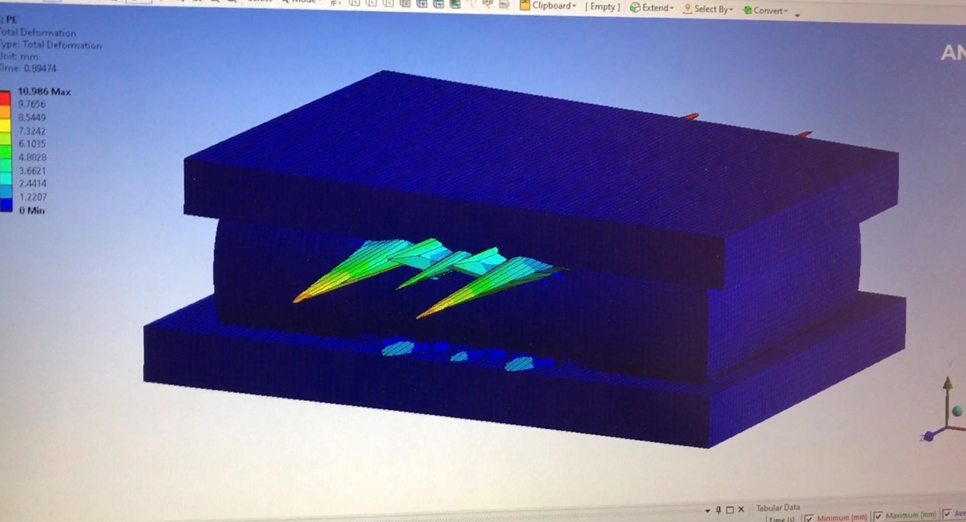 Second try PE result (unconverged, stopped at 82%):n
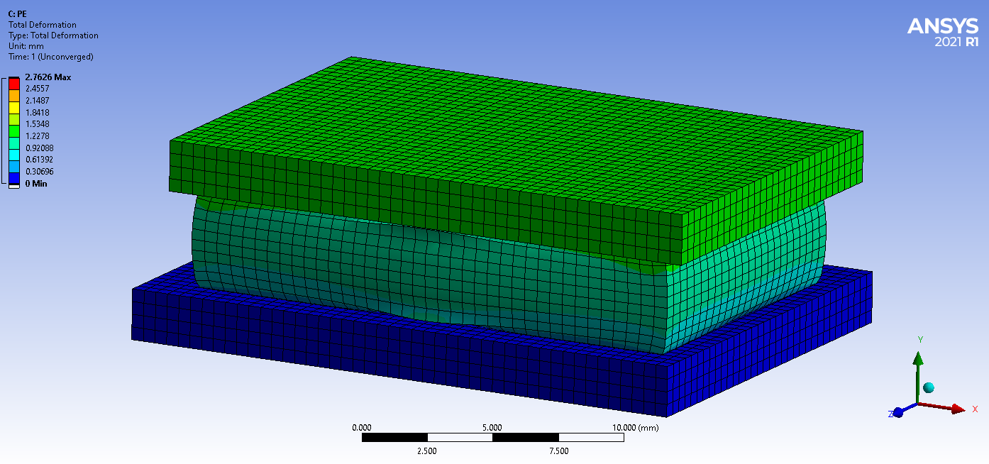 The reason according to solver output is element violations. Newton-raphson residuals and element violations are as follow:n
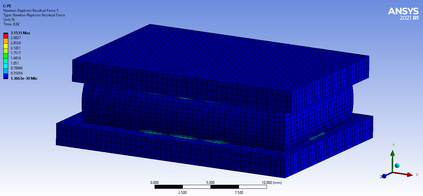
 Would you have any suggestion on how to handle high deformation of linear materials with a high poissons value in Ansys mechanical, whether it's possible?.Thanks again,nMonin
March 26, 2021 at 12:26 am
Would you have any suggestion on how to handle high deformation of linear materials with a high poissons value in Ansys mechanical, whether it's possible?.Thanks again,nMonin
March 26, 2021 at 12:26 ammrife
Ansys EmployeeNot to argue with but you may want to look at changing the allowable penetration instead of the contact stiffness factor. Penalty based contact methods (like Pure Penalty and Augmented Lagrange) require contact penetration, then a force is applied to pull the parts back to a just touching state. But there is a allowable penetration distance [FTOLN]; the default is 10% of the underlying solid element depth. You can run the model as is, then add a load step and change the allowed penetration amount to get a more accurate contact representation. On the contact pair change the Behavior to asymmetric (so only one pair will be created). Then right-click and insert a commands object. The CO should contain the command:ncontact1=_cidnAdd a Load Step to the analysis settings. Insert a command object to the environment (where loads are defined) and enter the following:nrmodif,contact1,4,.01nFTOLN is the fourth real constant of contact elements. So here it is setting it to be 1%. Be sure to set the CO to be applied to the last load step in its Details section. Solve and then compare in post-processing the contact results between the next to last and the last load step times.nMike np.s. here is a screen shot of an simple model example. FTOLN is change to 1% then to 0.1% The use of FTOLN is shown in an model in the Ansys Verification Manual; Mechanical APDL VM number 272 on Hertzian contact. I changed the geometry slightly in order to show a larger contact patch here.n n
March 26, 2021 at 1:02 amSubscriberMoni listen to Mike he knows more than me nMarch 30, 2021 at 8:25 amSubscriberThank you both . I'll do it and get back to you soon.nViewing 10 reply threads
n
March 26, 2021 at 1:02 amSubscriberMoni listen to Mike he knows more than me nMarch 30, 2021 at 8:25 amSubscriberThank you both . I'll do it and get back to you soon.nViewing 10 reply threads- The topic ‘Contact penetration’ is closed to new replies.
Innovation Space Trending discussions
 Top Contributors
-
peteroznewman
 5824
5824 -
scabo
 1906
1906 -
Dennis Chen
 1420
1420 -
javat33489
 1305
1305 -
Shyam Prasad V Atri
1021
Top Rated Tags
© 2026 Copyright ANSYS, Inc. All rights reserved.
Ansys does not support the usage of unauthorized Ansys software. Please visit www.ansys.com to obtain an official distribution.
-


The Ansys Learning Forum is a public forum. You are prohibited from providing (i) information that is confidential to You, your employer, or any third party, (ii) Personal Data or individually identifiable health information, (iii) any information that is U.S. Government Classified, Controlled Unclassified Information, International Traffic in Arms Regulators (ITAR) or Export Administration Regulators (EAR) controlled or otherwise have been determined by the United States Government or by a foreign government to require protection against unauthorized disclosure for reasons of national security, or (iv) topics or information restricted by the People's Republic of China data protection and privacy laws.
