

-
-
February 26, 2021 at 6:30 pm
Zhi Li
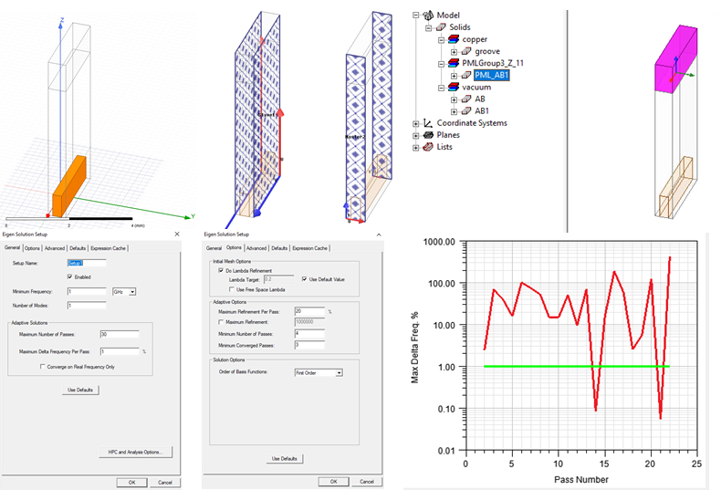
SubscriberHi, I have been trying to run some eigenmode simulation in HFSS to do dispersion analysis for periodic structures. The problem I met is that the Maximum Delta Frequency Per Pass oscillates over passes and does not converge during simulation in many of my designs. Attached is an example which includes the model, boundaries, the setup, and the convergence graph. The phase delay across boundaries along X-axis is set to 0° and the phase delay along Y-axis is assigned to a variable to be varied. In this particular simulation, the variable is 175°.
March 1, 2021 at 3:47 amAndyJP
SubscriberIf it ocillates, that means the mesh is not fine enough. Give it more passes. The delta is not some smooth function. It can get zero even at the second step by chance. n>The phase delay across boundaries along X-axis is set to 0?naha, that means a flat plane wave... or the next mode with 2pi...there's some uncertainty. Why would you need that? Leave it as ABC radiation, PML, or some symmetry boundary.n>Y-axis is assigned to a variable to be variednthat's how it is done when getting a dispersion curve.nMarch 1, 2021 at 3:29 pmSubscriberHi AndyJP,nnThank you for the comments! Will try them out. Regarding your second comment, I was trying to emulate an infinite extension along X-axis. What is your suggestion if I want to realize that in simulation?nMarch 2, 2021 at 12:24 amSubscriberno, you can use the strict definition for transverse (X) component, but you should be sure that the solved mode phase vector is strictly parallel to Y; and it may be not. There may be two degenerate modes with counterdirected oblique vectors, and you will miss them.nIn that case, I don't know, maybe an initial check with a larger X dimension, and radiative/PML boundaries, PMC maybe, since it is not so strict.nMarch 4, 2021 at 4:14 pmSubscriberHi AndyJP,nnI ran the simulation with finer meshes. It seems finer meshes over more passes can help with convergence. In addition, another issue comes into my view. Since the solution frequency is complex, we need to understand the physical meaning of both real and imaginary parts. From one paper I read, the imaginary part, when it is greater than zero, represents the attenuation of field over time. However, I have seen the eigenmode solver returns solution frequencies with a negative imaginary part. In that case, if we use the same interpretation above, it would represent amplification of fields over time, which is not physically possible. May I know your opinion on the imaginary part of the complex solution frequency being negative?nMarch 5, 2021 at 6:37 pmPraneeth
Ansys EmployeeHi @zlEM,nDid you try solving your simulation model using driven solution?nIf so, please share your results.nAll the very best.nBest Regards,nMarch 5, 2021 at 8:13 pmSubscriberHi Array,nI tried but the overall structure simulated in driven mode, as shown in the attached figure [1], is different from the target structure in eigenmode. The reason is that the mode I want to study/use cannot be excited efficiently using plane waves. The waveguide section and the transition in between the waveguide and the target structure are used to physically and efficiently excite the mode. As a result, due to the existence of discontinuity, I could not deembed to get a pure dispersion relation of the target structure from driven mode solution data, which is the motivation of me doing the eigenmode analysis.n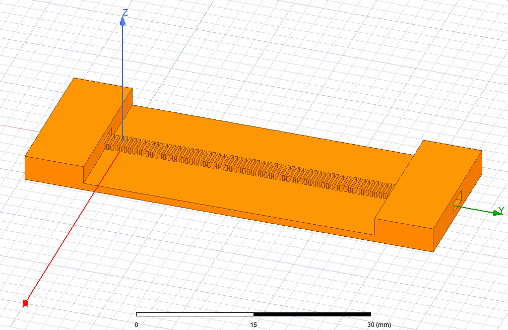 nThank you.n[1] Q. L. Zhang, B. J. Chen, K. F. Chan and C. H. Chan, High-Gain Millimeter-Wave Antennas Based on Spoof Surface Plasmon Polaritons, in IEEE Transactions on Antennas and Propagation, vol. 68, no. 6, pp. 4320-4331, June 2020, doi: 10.1109/TAP.2020.2970122.n
March 8, 2021 at 1:39 amSubscriber>May I know your opinion on the imaginary part of the complex solution frequency being negative?nIf I am not mistaken, that may mean 3 things 1)damping, where imaginary part of f is transferred to the real part of propagation constant (i.e. loss factor) 2)radiative leaking, and 3)the mode's wave vector is oblique to the linked boundaries or other model inconsistency.nIf you did not define lossy materials in your model, you can safely exclude case (1) from the list. Absence of radiating boundaries excludes case (2)nMarch 8, 2021 at 4:09 amSubscribernThank you for your comments. They seem to be logical explanations.nMarch 10, 2021 at 3:02 pmAnsys EmployeenI could not think of why you are using primary and secondary boundaries (master and slave) unless you are trying different from the reference paper.nBut if you are trying to solve as per the paper then you can have one air box surrounding the model and then simulating it using the Eigenmode solver.n
nThank you.n[1] Q. L. Zhang, B. J. Chen, K. F. Chan and C. H. Chan, High-Gain Millimeter-Wave Antennas Based on Spoof Surface Plasmon Polaritons, in IEEE Transactions on Antennas and Propagation, vol. 68, no. 6, pp. 4320-4331, June 2020, doi: 10.1109/TAP.2020.2970122.n
March 8, 2021 at 1:39 amSubscriber>May I know your opinion on the imaginary part of the complex solution frequency being negative?nIf I am not mistaken, that may mean 3 things 1)damping, where imaginary part of f is transferred to the real part of propagation constant (i.e. loss factor) 2)radiative leaking, and 3)the mode's wave vector is oblique to the linked boundaries or other model inconsistency.nIf you did not define lossy materials in your model, you can safely exclude case (1) from the list. Absence of radiating boundaries excludes case (2)nMarch 8, 2021 at 4:09 amSubscribernThank you for your comments. They seem to be logical explanations.nMarch 10, 2021 at 3:02 pmAnsys EmployeenI could not think of why you are using primary and secondary boundaries (master and slave) unless you are trying different from the reference paper.nBut if you are trying to solve as per the paper then you can have one air box surrounding the model and then simulating it using the Eigenmode solver.n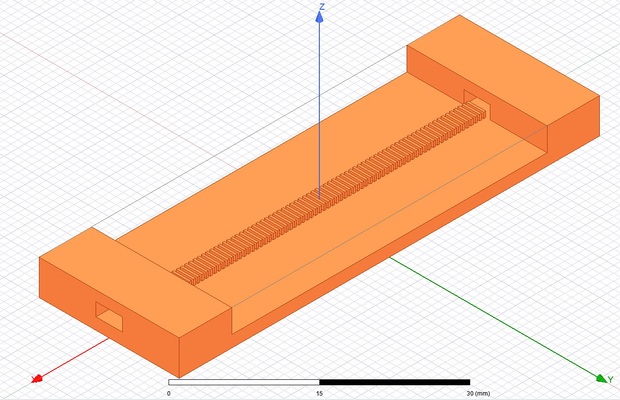 All the very best.nBest Regards,n
March 10, 2021 at 10:09 pmSubscribernThank you for your suggestion. I will try that.nZhinViewing 10 reply threads
All the very best.nBest Regards,n
March 10, 2021 at 10:09 pmSubscribernThank you for your suggestion. I will try that.nZhinViewing 10 reply threads- The topic ‘Convergence Issue with HFSS Eigenmode Simulation’ is closed to new replies.
Innovation Space Trending discussions
 Top Contributors
-
peteroznewman
 6520
6520 -
scabo
 1906
1906 -
Dennis Chen
 1463
1463 -
javat33489
 1310
1310 -
Shyam Prasad V Atri
1022
Top Rated Tags
© 2026 Copyright ANSYS, Inc. All rights reserved.
Ansys does not support the usage of unauthorized Ansys software. Please visit www.ansys.com to obtain an official distribution.
-


The Ansys Learning Forum is a public forum. You are prohibited from providing (i) information that is confidential to You, your employer, or any third party, (ii) Personal Data or individually identifiable health information, (iii) any information that is U.S. Government Classified, Controlled Unclassified Information, International Traffic in Arms Regulators (ITAR) or Export Administration Regulators (EAR) controlled or otherwise have been determined by the United States Government or by a foreign government to require protection against unauthorized disclosure for reasons of national security, or (iv) topics or information restricted by the People's Republic of China data protection and privacy laws.

 You are navigating away from the AIS Discovery experience