
-
-
November 27, 2020 at 7:56 am
anuragk91299
Subscriber- tool material: gray cast iron
- work piece: AISI 1045
- Procedure: establishing cylindrical coordinate system for work piece and displacing it for 360 degree i.e. 1 rotation for a feed of 5 mm. further
- issues: 1. instead of the work piece, tool undergoes cutting (work piece acts like the tool) 2. how can i give the work piece an angular velocity while the tool cuts?
Please do help.
regards
PFA the files if you want to take a look at the soltuion
November 27, 2020 at 8:45 pmSubscriberplease do give a looknNovember 27, 2020 at 9:28 pmpeteroznewman
SubscribernWhat version of ANSYS are you using?nNovember 27, 2020 at 11:07 pmSubscribernYou put the .wbpj file in the .rar archive. The .wbpj file is useless without the _files folder of the same name.nOpen the project in Workbench, and use the File, Archive menu to save a .wbpz file. This is an archive that puts both the .wbpj file and the _files folder into a single file.nI can't look at your model until you upload this archive.nNovember 28, 2020 at 5:30 amSubscriberVersion 19.2nThe .wbpz file is too large for the forum, please find attached the drive linknnNovember 29, 2020 at 4:39 amSubscribernI modified your model to attempt to do just one thing: rotate the workpiece. In order to get a mesh that would solve quickly, I put a hole in the workpiece. nI assigned an Angular Velocity in the Initial Conditions of 36.7 rad/s which is about 350 rpm.n Using the Cylindrical Coordinate System, I assigned a 1800 degree rotation about Z by using the Y coordinate of the cylindrical coordinates to be spread over 0.856 s which is a speed of 350 rpm and in that time it will make 5 revolutions.n
 Even though it doesn't seem like a great accomplishment to rotate a tube, look at the link below to find out that two other methods of doing this simple task fail completely!nwill be glad to know this works. /forum/discussion/22283/a-solid-tube-rotating-at-a-constant-350-rpm-erodes-itself-whyn
November 29, 2020 at 5:17 amSubscribernThank you so much sir.nwhat can you suggest regarding the cutting of the workpiece ? The tool isn't cutting the workpiece nNovember 29, 2020 at 5:26 amSubscriberI'm simulating that now. I will let you know tomorrow. But your model has solved a problem I have had for several weeks. The key was the cylindrical coordinate system.nIn your original model, your end time was 0.0005 s for 1 revolution. That is 120,000 rpm. What lathe turning handbook has spindle speeds that high? I still don't believe the 5 mm you set to travel in that time. That is a velocity of 10 m/s. You won't find numbers like that in any metal cutting handbook that I know of.nNovember 29, 2020 at 8:01 amSubscriberActually i was going through some YouTube videos of turning operation where the engineer that was performing used the end time of 0.0005s for 1 revoltion and gave a 4mm feed. We are finding the numbers as of now in the handbook. My first aim as of now is just to perform a normal cutting operation (turning) which would be the base of my project and further on I'll be substituting values from the metal cutting handbook for my experiment table. please do let me know if get the simulation done.nnThank YounNovember 29, 2020 at 1:48 pmSubscribernUsing more reasonable values, the tool is now cutting the workpiece. I made the tool material be Structural Steel.n
Even though it doesn't seem like a great accomplishment to rotate a tube, look at the link below to find out that two other methods of doing this simple task fail completely!nwill be glad to know this works. /forum/discussion/22283/a-solid-tube-rotating-at-a-constant-350-rpm-erodes-itself-whyn
November 29, 2020 at 5:17 amSubscribernThank you so much sir.nwhat can you suggest regarding the cutting of the workpiece ? The tool isn't cutting the workpiece nNovember 29, 2020 at 5:26 amSubscriberI'm simulating that now. I will let you know tomorrow. But your model has solved a problem I have had for several weeks. The key was the cylindrical coordinate system.nIn your original model, your end time was 0.0005 s for 1 revolution. That is 120,000 rpm. What lathe turning handbook has spindle speeds that high? I still don't believe the 5 mm you set to travel in that time. That is a velocity of 10 m/s. You won't find numbers like that in any metal cutting handbook that I know of.nNovember 29, 2020 at 8:01 amSubscriberActually i was going through some YouTube videos of turning operation where the engineer that was performing used the end time of 0.0005s for 1 revoltion and gave a 4mm feed. We are finding the numbers as of now in the handbook. My first aim as of now is just to perform a normal cutting operation (turning) which would be the base of my project and further on I'll be substituting values from the metal cutting handbook for my experiment table. please do let me know if get the simulation done.nnThank YounNovember 29, 2020 at 1:48 pmSubscribernUsing more reasonable values, the tool is now cutting the workpiece. I made the tool material be Structural Steel.n
 This was solved using ANSYS 2020 R1. The mesh size exceeds the Student license limits. I have access to ANSYS 19.2 in a Student license.n
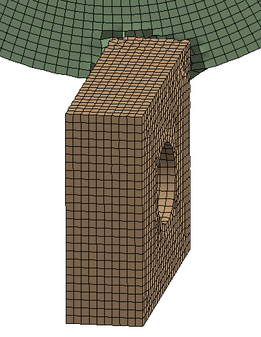
November 29, 2020 at 5:56 pmSubscriberthank you so much sir. What changes did you do ? Also can you share the source file so that I can take a look at the simulation and try to produce something similar as per the cutting operation standards.nThank you so much sir, really appreciate itnNovember 30, 2020 at 6:07 amSubscriberIs there any way we ca reduce the clock time? Because as of now we only considered the insert edge... But when it comes to force analysis, and merchant circle, the rake angle plays an important role which is mainly given with the help of the tool holder. so we'll be including the the holder as well. which will increase the solving time. Is there any way to overcome that??nNovember 30, 2020 at 12:00 pmSubscriberplease do reply...nnNovember 30, 2020 at 2:04 pmSubscriber@anuragk91299, nYou can tilt the tool insert to create a rake angle. You don't need the tool holder in the simulation.nThe number of elements is not the most important factor in reducing elapsed time of the simulation. The most important factor is the minimum Element Characteristic Length. Read some of these discussions to learn more.nArrayHex elements are not always the best elements. There is a defect that can enter the simulation results called 'hourglass mode'. The image below shows what the mesh looks like before the simulation starts.n
This was solved using ANSYS 2020 R1. The mesh size exceeds the Student license limits. I have access to ANSYS 19.2 in a Student license.n
November 29, 2020 at 5:56 pmSubscriberthank you so much sir. What changes did you do ? Also can you share the source file so that I can take a look at the simulation and try to produce something similar as per the cutting operation standards.nThank you so much sir, really appreciate itnNovember 30, 2020 at 6:07 amSubscriberIs there any way we ca reduce the clock time? Because as of now we only considered the insert edge... But when it comes to force analysis, and merchant circle, the rake angle plays an important role which is mainly given with the help of the tool holder. so we'll be including the the holder as well. which will increase the solving time. Is there any way to overcome that??nNovember 30, 2020 at 12:00 pmSubscriberplease do reply...nnNovember 30, 2020 at 2:04 pmSubscriber@anuragk91299, nYou can tilt the tool insert to create a rake angle. You don't need the tool holder in the simulation.nThe number of elements is not the most important factor in reducing elapsed time of the simulation. The most important factor is the minimum Element Characteristic Length. Read some of these discussions to learn more.nArrayHex elements are not always the best elements. There is a defect that can enter the simulation results called 'hourglass mode'. The image below shows what the mesh looks like before the simulation starts.n In the image below, the hourglass defect has gotten very bad in the hex mesh. n
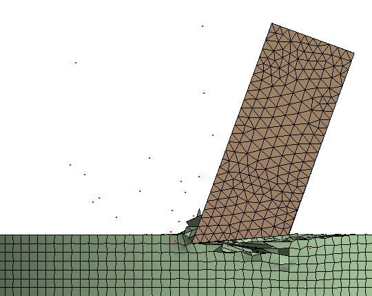
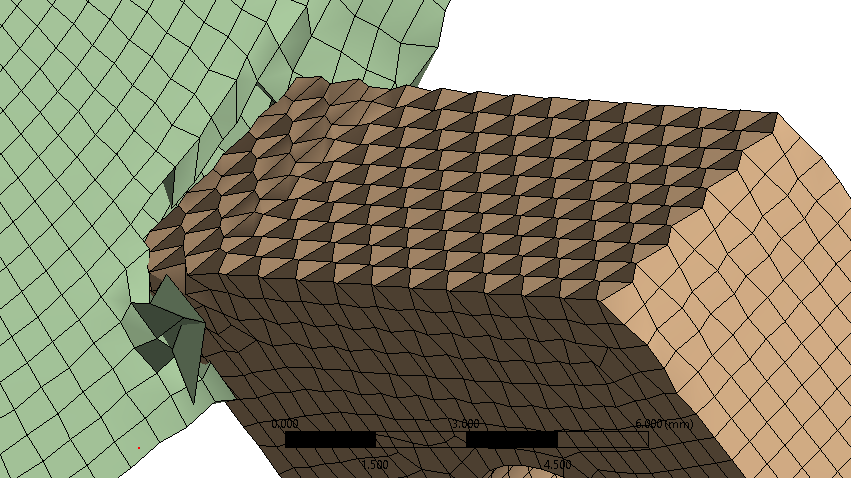 nI changed the mesh on the tool to Tetrahedrons that don't suffer from hourglass mode and the simulation will perform better. The image below shows what the mesh looks like before the simulation starts.n
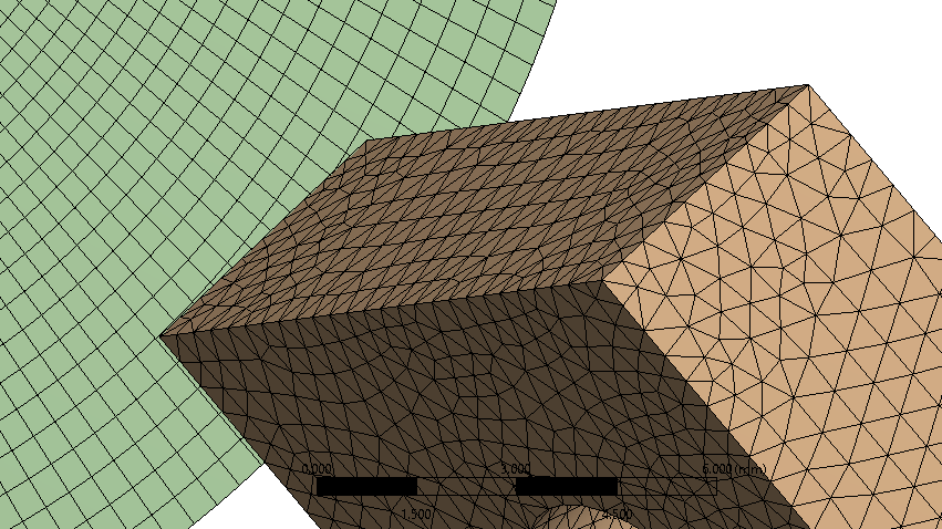 In the image below, the simulation has run for a short time but the tool it in good shape.n
 November 30, 2020 at 4:37 pmSubscriberArrayCan you please share the source file for reference? also what would you suggest about the low step time error. I guess i'm getting issues in the analysis settings. Please do let me know what to donNovember 30, 2020 at 6:52 pmSubscriberI was using ANSYS 2020 R1. If you are using 19.2 you won't be able to open my files. Can you upgrade to 2020 R1?nDecember 1, 2020 at 4:23 amSubscriberwould the student version work? I am having issues in the time step and energy errors, Basically Analysis settings. Would the student version 2020 work?.December 1, 2020 at 4:25 amSubscriberThe available version as of now for students is 2020 R2. Would that work???.December 1, 2020 at 4:25 amSubscribernDecember 1, 2020 at 12:16 pmSubscriberDecember 1, 2020 at 12:42 pmSubscriberNo Sir i did not change anything, It was defaulted at 0.1 and later on I started getting time step error as wellnDecember 1, 2020 at 12:44 pmSubscribernYou can set it to 10 and it should run without error. You can plot the Energy after it solved and see if the error is acceptably small.nDecember 1, 2020 at 12:47 pmSubscriberThank you so much, you've been a great help. If anything pops up I'll keep posting on the forum... Thanks Again ! do let me know about the analysis setting though.n nDecember 6, 2020 at 10:25 amSubscriberArray nHello sir,nI solved the simulation in the you sent by changing the values for further testingnnThen after a while, I imported my own CAD file where after which I followed the same steps but experienced this error Cannot transfer loads and constraints to the solvernChecked the solution information which mentioned nRemote Points found - FailednnArray please do help and let me know what can be done.nnThe only that changed in the CAD file is the the addition of rake and relief anglennDecember 6, 2020 at 1:42 pmSubscribernThe model I run does not use Remote Points. Take them out and replace with Displacements.n
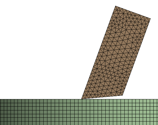
 December 6, 2020 at 5:30 pmSubscriberArraySir, I can see that you are not taking nose radius into consideration whereas I am (0.4 mm). Is that why I am getting the issue? Please do elaborate on the same.nnPardon me but The error is No remote points found. What can be done in that case?.please do reply to the earliest Array Thank you so much SirDecember 6, 2020 at 5:38 pmSubscribernI did not include a nose radius. That has nothing to do with the error which refers to Remote Displacement.nDecember 6, 2020 at 5:46 pmSubscriberWhat should be done? Should I include remote displacement instead of displacement?nDecember 6, 2020 at 5:51 pmSubscriberArray also the error other says that non zero initial displacement in y direction (which is the spindle rotation 1800 degree) is not applicable in explicit dynamicsnDecember 6, 2020 at 6:32 pmSubscribernIn the Displacement BC, is the Cylindrical Coordinate System selected?nIs the Displacement set to (ramped) where the value of the Y component of displacement is 0 at t=0 and 1800 at t=0.856 s ?n
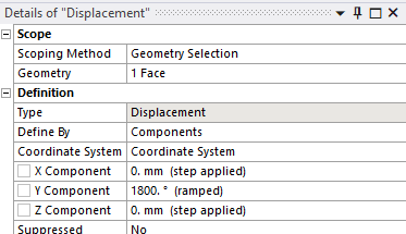
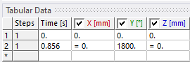 December 7, 2020 at 5:34 amSubscriberSir this is what I'm getting... Ramped for all three... X Y ZnnDecember 7, 2020 at 5:35 amSubscribernDecember 7, 2020 at 6:35 pmSubscribernRamping from 0 to 0 is the same as constant. Don't worry about that. Look at the Tabular Data, does it look like mine?nDecember 8, 2020 at 8:02 amSubscriberIt wasn't at first. Had to change the values manually in the table. Kept it to solve as of now. It takes time on my laptop as its 2 years old. i5 8th gen and 1050ti GPUnnI'll keep you updated sir.nThank younDecember 10, 2020 at 6:34 pmSubscriberHello SirnStill facing the same issue where the tool is being cut by the workpiece when I've added nose radius, rake angle and relief angle. Can you please help me out Sir.nplease reply ASAP nthank younnDecember 10, 2020 at 7:47 pmSubscribercan you help me out... like show me what to do or share your source file like before using the new cad model (attached in the comment above) because further ahead we will be changing the rake angles and relief angles to see their effect on the forces and deformation so this would just speed up our process very fastnplease do help me out nregardsDecember 11, 2020 at 6:06 amSubscribernDecember 11, 2020 at 11:21 amSubscriberSir please do replynDecember 11, 2020 at 11:10 pmSubscribernAttached is my ANSYS 2020R1 model with a rake angle of 20 degrees.n
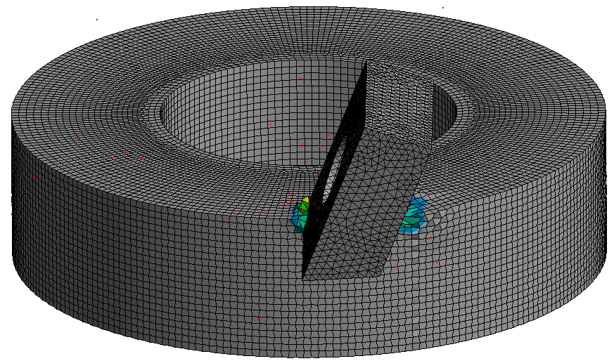 n
Viewing 38 reply threads
n
Viewing 38 reply threads- The topic ‘Can anyone help me to do explicit dynamics for turning operation’ is closed to new replies.
Ansys Innovation Space Trending discussions
 Top Contributors
-
peteroznewman
 3882
3882 -
scabo
 1414
1414 -
Dennis Chen
 1241
1241 -
javat33489
 1118
1118 -
Shyam Prasad V Atri
1015
Top Rated Tags
© 2025 Copyright ANSYS, Inc. All rights reserved.
Ansys does not support the usage of unauthorized Ansys software. Please visit www.ansys.com to obtain an official distribution.
-


The Ansys Learning Forum is a public forum. You are prohibited from providing (i) information that is confidential to You, your employer, or any third party, (ii) Personal Data or individually identifiable health information, (iii) any information that is U.S. Government Classified, Controlled Unclassified Information, International Traffic in Arms Regulators (ITAR) or Export Administration Regulators (EAR) controlled or otherwise have been determined by the United States Government or by a foreign government to require protection against unauthorized disclosure for reasons of national security, or (iv) topics or information restricted by the People's Republic of China data protection and privacy laws.


