

-
-
November 21, 2020 at 1:14 pm
KKBH
SubscriberFor an IPM motor, I want to look at the forces on the rotor while it is running. But magnetostatic and transient simulations are giving me different results? I am using Electronic desktop 2019.
Left side pictures are transient simulation and right side are magnetostatic. The mesh settings for both simulations are same. Torque matches nicely, but force is not making any sense.
November 23, 2020 at 4:30 pmNavya Chode
Forum ModeratorHi,
What is your excitation setup for winding in both cases? are you providing any excitation to the windings in both cases or are you just checking the cogging torque in un excited state?
Results will be same only in the winding unexcited state.
If you are exciting the windings in transient simulation, torque in both the cases will not be same as magnetostatics simulation is a DC-magnetic simulation
Observation from torque graph you shared - for a transient simulation the torque graph should ramp up from zero to steady state. But what you shared is starting from some initial value at 0 time.
Regards
Navya
November 23, 2020 at 5:05 pmSubscriberI am injecting some Iq current with Id=0 in both cases. That's why there is an average torque and cogging torque can be seen on top of that.
Both simulations have same equivalent excitation (current depending on rotor position), that's why the torque produced is same.
The problem is I am not sure whether applying Iq current to the motor will produce force on the rotor. Since both simulations are giving different results.
Thanks
December 3, 2020 at 1:15 pmForum ModeratorHi,
Whether it is transient or static simulation the resultant torque could be approximately same. This is because torque is angular twist acting, due to the whole airgap magnetic field, on the rotor at any instance.
But when it comes to force what you are looking is at a particular position along the x or y axis .
Here there is a difference between transient and static simulation
In transient simulation you have a motion setup and position of the rotor is changing with respect to time and force along the axis is captured continuously with time varying fields.
Where as in static simulation the rotor is static at a particular position at each step and it will not take continuous variation with time in to account(static simulation can't take time varying field in to account). So, it will be different.
If you think there is some misinterpretation of what you are simulating, please consider sharing some screen shots that will explain your excitation and motion setup for both simulations explaining how you defined Iq current with Id=0 in both cases as clear as possible.
Note: Ansys employees can't access any attachments (pictures/documents/simulation files) shared in the learning forum. Kindly use upload image option while inserting any images.
Regards
Navya
December 7, 2020 at 3:56 pmSubscriber.Hi
I understand static simulation will not capture changing fields. That's why I ran the transient simulation with 30rpm/ 1Hz excitation, such that any field change should settle before next step.
Is there any way to send you the simulation file?
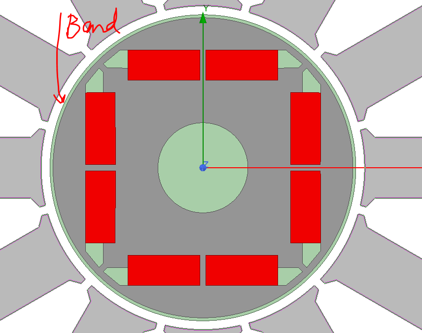
For transient simulation, I setup band for motion as shown below. The speed is 30rpm and excitation is simply 3 phase sinusoidal current with 1Hz frequency.
I assigned Force parameter on the rotor core and magnets collectively.
Current Excitation is 100*sin(2*pi*1*time) and corresponding for other 2 phases.
For magnetostatic simulation, I used same topology, but assigned Force and torque parameters to the rotor core and magnets collectively.
I also parametrize the rotor rotation angle as Thetaz.
And assign excitation as 100*sin(Thaetaz + phi0) and correspondingly for other phases. phi0 is used to orient the current in the q axis.
.January 27, 2022 at 10:10 amel4ezc
Subscriber.`And assign excitation as 100*sin(Thaetaz + phi0) and correspondingly for other phases. phi0 is used to orient the current in the q axis.`
how did you do that? Could you explain more please?
.Viewing 5 reply threads- The topic ‘Force mismatch in Magnetostatic and Transient SImulation’ is closed to new replies.
Innovation Space Trending discussions
 Top Contributors
-
peteroznewman
 6269
6269 -
scabo
 1906
1906 -
Dennis Chen
 1457
1457 -
javat33489
 1308
1308 -
Shyam Prasad V Atri
1022
Top Rated Tags
© 2026 Copyright ANSYS, Inc. All rights reserved.
Ansys does not support the usage of unauthorized Ansys software. Please visit www.ansys.com to obtain an official distribution.
-
Ansys Assistant will be unavailable on the Learning Forum starting January 30. An upgraded version is coming soon. We apologize for any inconvenience and appreciate your patience. Stay tuned for updates.


