-
-
November 1, 2020 at 3:24 am
ChomanSalih
SubscriberHi, I am new to Ansys and I have a simple question (I believe). I want to model a beam resting an elastic foundation. I mean insert elastic support>selct bottom face>unput foundation stiffness. nI have modeled and validated this with given analytical equations on Strand 7 with line body. However, I want to model it as a 3d object and when I model the beam as a 3d object in Ansys, I cannot insert the beam results tool in the solution part (the option is not there anymore). I modeled the beam as rexctangular cross section then extrude to the desired length. nThere are many videos on Youtube about shear and bending moment diagrams, but they are all for line bodies with defined cross section. I can do that too but the issue that I have is I cannot insert elastic support for the line body. It just doesnt recognise the 3d beam for the elastic support when modeled as a line. nCan anyone suggest how to model a 3d beam with elastic support with the ability of drawing the bending moment diagram along the beam (along x, around z axis)? nI am using Ansys Workbench 2020 R1nthank you n -
November 3, 2020 at 12:41 am
Kai
Ansys EmployeeHi Array , when you model the beam like geometry with beam 188 element (1D beam), Ansys will be using Timoshenko beam theory to do FEA and provides some easy tools for users to extract beam related results under beam tool. When you model the beam like geometry with solid elements such as solid186, Ansys doesn't know the geometry is a beam. Instead, it will treat it as a regular 3D geometry. For this reason, we don't have any beam tools for 3D geometry. What you may do is to extract force reaction and moment reaction under "probe" along different "surface" (construction geometry). This may give you bending moment diagram.
-
July 3, 2021 at 10:00 am
pdvelani
Subscriber.Hello, Kai and ChomanSalih : I am facing the same challange. Also, I could not implement the solution suggested by Kai. Can anyone of you please elaborate the solution or guide me to some resource please?
. -
July 5, 2021 at 11:06 am
-
July 5, 2021 at 11:17 am
ErKo
Ansys Employee.Hi
First use a surface that is along the zy plane (we need the x nodal forces that cause the moment about global z) - finally under analysis settings, and output controls, set all to yes (so nodal forces, etc).
Finally to generate the internal moments along that part, we would need to have several surfaces and then several moment reaction results (scoped to these different surfaces) in order to get the moment reaction along different locations along the beam.
All the best
Erik
. -
July 5, 2021 at 11:26 am
-
July 5, 2021 at 11:55 am
-
July 5, 2021 at 1:57 pm
-
July 5, 2021 at 2:08 pm
-
July 5, 2021 at 2:14 pm
-
July 6, 2021 at 10:05 am
pdvelani
Subscriber.peteroznewman ekostson
Thank you for your response. I could generate the Bending Moment values.
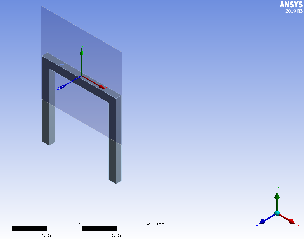
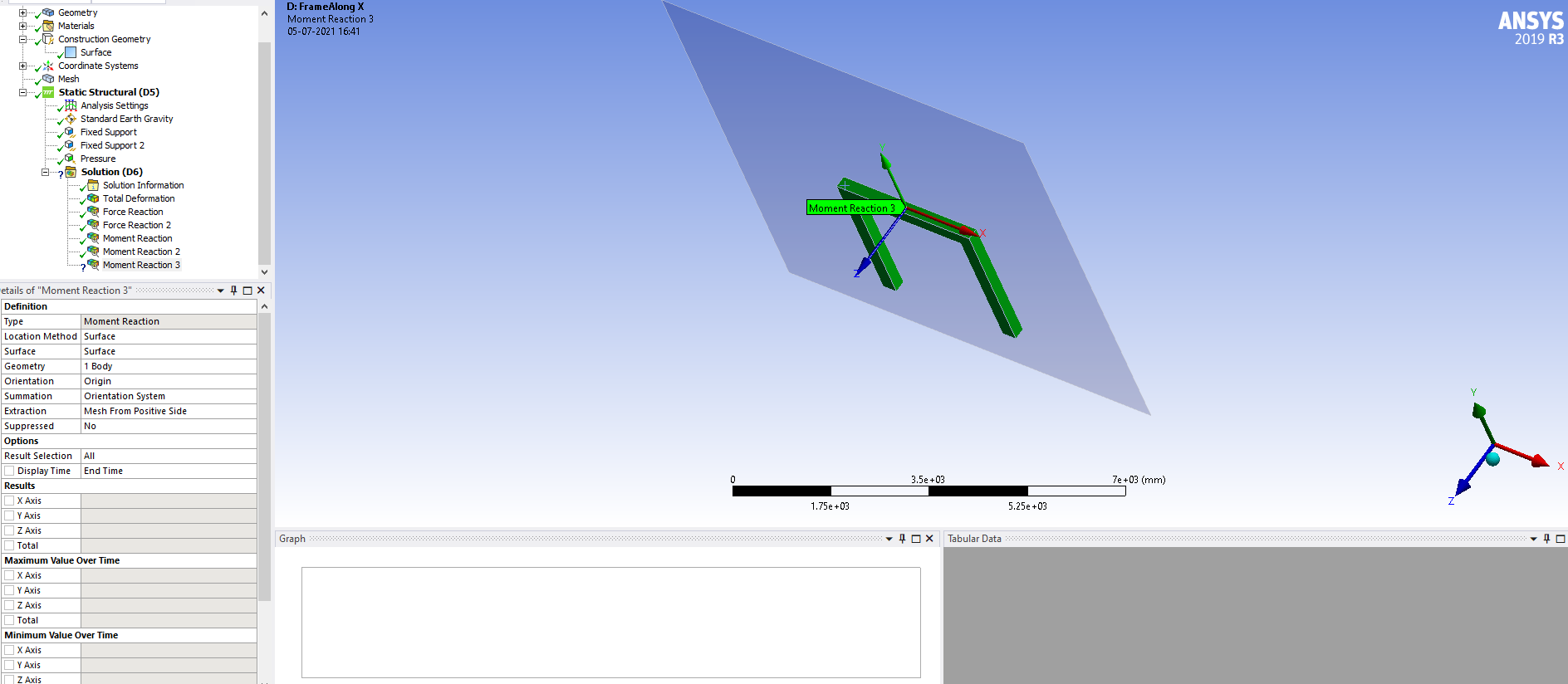
However, I need small clarification/insight regarding the results. I am creating different "origins" at the start, at quarter length, at the midpoint, and at end of a beam as shown below.
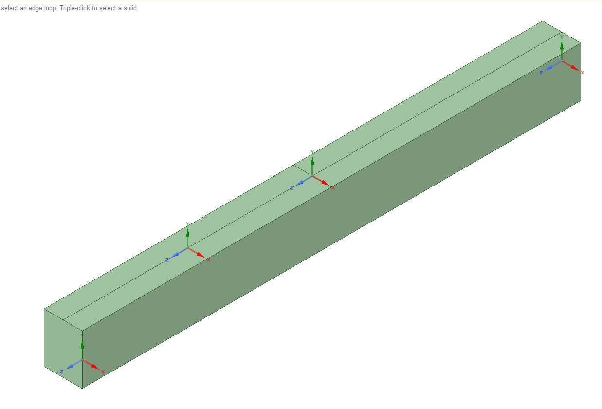
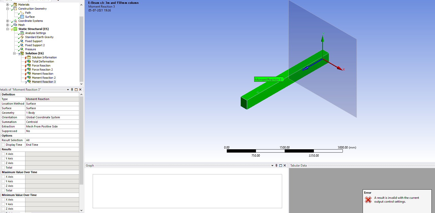
The surfaces are created at respective origins and bending moment values are generated. To my surprise except at the midpoint rest 3 locations the answers are not satisfactory. The values at start and end origins are not matching with the moment generated for the "Boundary condition".
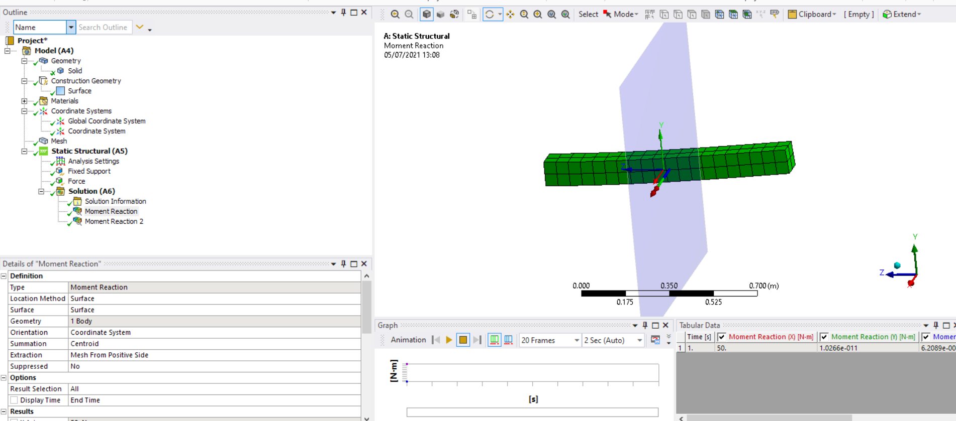
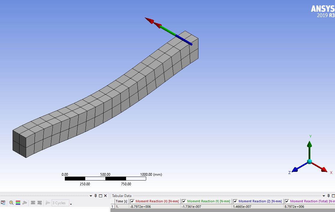
Correct values based on boundary condition --> -8.79 kN.m
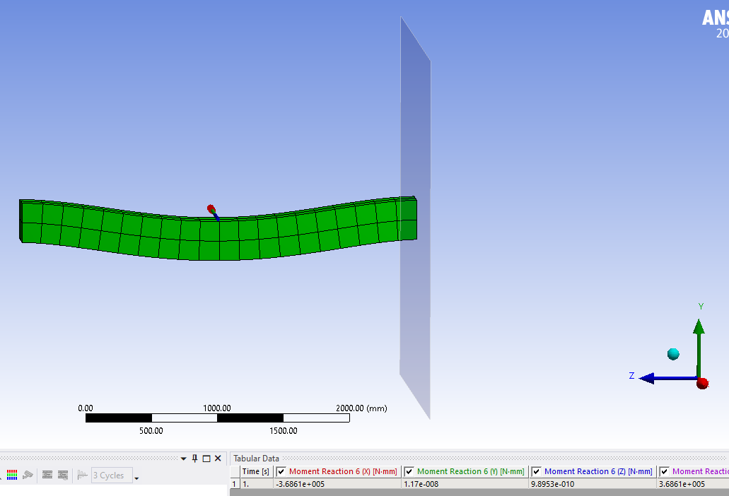
Inoorrect values based on surface--> - 3.686 kN.m
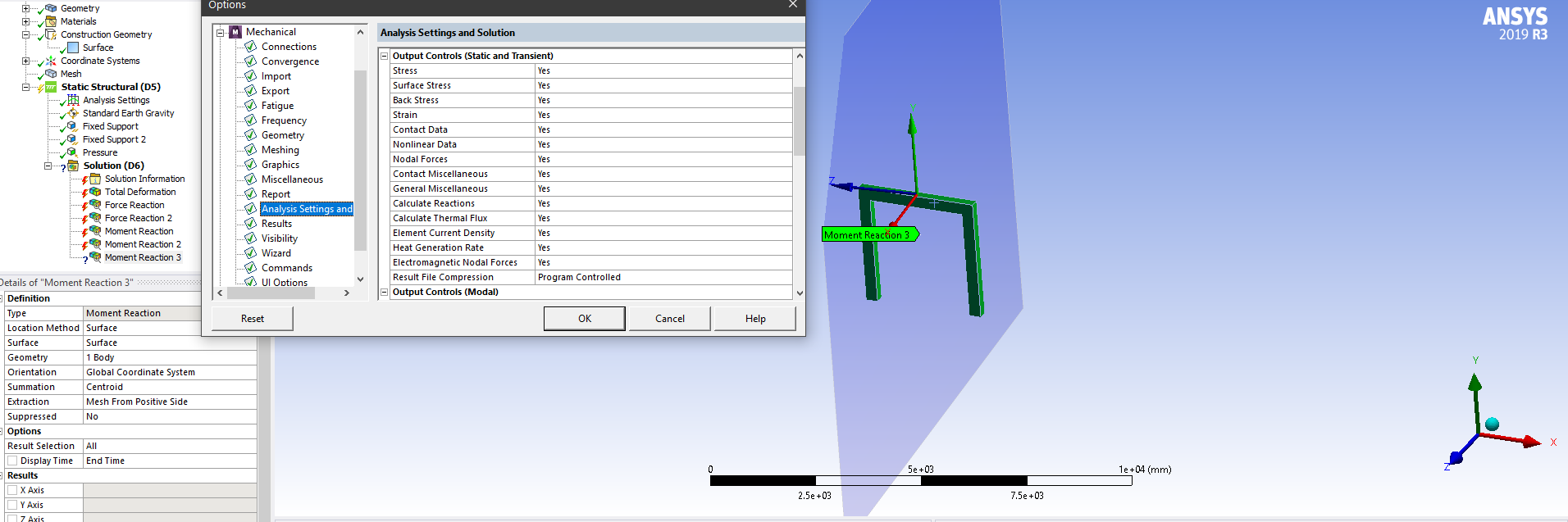
Can you guide me in fixing the possible error in modelling?
Further, Do I have to construct a number of origins and surfaces at all desire locations where I need Bending Moments? Is there any better way to construct Bending moments at many locations other than what we are discussing now?
. -
July 6, 2021 at 10:39 am
ErKo
Ansys Employee.That is good.
Further, Do I have to construct a number of origins and surfaces at all desire locations where I need Bending Moments? Is there any better way to construct Bending moments at many locations other than what we are discussing now?
Yes
You should have a coordinate system for each surface and each location where we want the moment in/about.
. -
July 6, 2021 at 10:51 am
pdvelani
Subscriber.ekostson : Thank you. Any feedback on 1st question? Why there is a difference in values from "surface" and "Boundary condition" "moment reactions"?
. -
July 6, 2021 at 11:23 am
ErKo
Ansys Employee.One is the moment reaction on a boundary condition, and the one oe is the moment reaction taken where the surface is defined - so one would not use surface to get the moment at a boundary condition say fixed, we would use the boundary condition option, and ofcourse we need to use the surface option to get the reaction in the mesh and away from the boundary condition, say midway along the length of the beam.
All the best
Erik
. -
July 6, 2021 at 11:41 am
pdvelani
Subscriber.ekostson : Yes, I completely agree with your explanation.
To verify the bending moment I am generating a surface at 20 mm before the boundary condition (near the right end of beam). The bending moment at this point is 17.23 kN.m which should be less than - 8.79 kN.m (moment obtained at boundary condition). Hence, I am not yet confident about the result and suspect shortcomings in my modelling.
.
-
- The topic ‘Bending moment a long a beam’ is closed to new replies.
-
6485
-
1906
-
1458
-
1308
-
1022
© 2026 Copyright ANSYS, Inc. All rights reserved.


