-
-
October 3, 2020 at 9:09 am
Rameez_ul_Haq
SubscriberHello there. We all know the specified ranges for the element quality, aspect ratio, orthagonal quality and skewness for the mesh elements, to be classified as good elements for modelling. But how will a low quality element, or with high skewness and aspect ratio affect my results? What is the background of it? How will a 'bad element' will cause the stresses within my model at that location to become illogical and absurd? What is the theory? How can they result in stress singularities as well?nWill bad elements also cause the displacements at those locations to be affected as well?n -
October 4, 2020 at 12:40 pm
peteroznewman
SubscriberHello Array
A singularity is a characteristic of the geometry, such as an interior corner, and is independent of poor element shapes.
Low element quality affects stress much more than displacements. Stress is calculated from a difference of displacements, so small errors in displacement are magnified by the difference calculation.
Study the mathematical equations for the shape functions used in each element. These are created to work well for ideal element shapes, but the mapping from the ideal shape to the actual shape degrades the accuracy of those shape functions. There are more ways a quadratic element can go wrong than a linear element because the assumption is that a midside node is expected to at the center of the line connecting the corner nodes and it might stray far from that point. You don't need to know the details, since as you say, there are measurement tools with acceptable limits on the various metrics to allow you to judge the quality of the mesh.
Keep in mind that element quality metrics are only one source of error in the overall model. A much larger effect is discretization error, which occurs by using elements that are too large (but may have ideal shapes) in areas of high stress gradient. Another error is in over-simplified boundary conditions or connections between parts.
-
October 12, 2021 at 2:31 pm
Rameez_ul_Haq
Subscriber.peteroznewman, Hello sir. Thank you for the comment that you made here, which is a general idea of how would the element quality effect the results within the element.
I just wanted to make sure that even if I have low quality elements, but the displacements calculated at the nodes by solving the global stiffness matrix equation will still be 'kinda' accurate, right? Its just that the shape functions (while interpolating the displacements within the element, and then stresses from the Guass integration points onto the element) will suffer because of the element's low quality, right? Or since each of the elemental stiffness matrix of an element itself has an influence of the shape functions, so the calculated displacements' accuracy also depends on the elemental quality?
"but the mapping from the ideal shape to the actual shape degrades the accuracy of those shape functions.", did you just imply that the shape functions (which are pre-implanted into the FEA softwares) of an element are transformed to the actual element shape within my model, and that is why its accuracy is dependent on the element quality?
"There are more ways a quadratic element can go wrong than a linear element because the assumption is that a midside node is expected to at the center of the line connecting the corner nodes and it might stray far from that point", how? I mean a quadratic element has a property that makes the midside nodes should always be in the mid of the line connecting two nodes, isn't it?
. -
October 13, 2021 at 3:43 am
peteroznewman
Subscriber.Rameez_ul_Haq
"but the mapping from the ideal shape to the actual shape degrades the accuracy of those shape functions.", did you just imply that the shape functions (which are pre-implanted into the FEA softwares) of an element are transformed to the actual element shape within my model, and that is why its accuracy is dependent on the element quality?
Yes, exactly. An example of the transformation is on slide 17 of this pdf.
https://www.geophysik.uni-muenchen.de/~igel/Lectures/NMG/08_finite_elements_basisfunctions.pdf
"There are more ways a quadratic element can go wrong than a linear element because the assumption is that a midside node is expected to at the center of the line connecting the corner nodes and it might stray far from that point", how? I mean a quadratic element has a property that makes the midside nodes should always be in the mid of the line connecting two nodes, isn't it?
In the link below, they deliberately put the midside node at the 25% position instead of 50% to cause a singularity at the crack tip for the Linear Elastic Fracture Mechanics solution to be more accurate.
https://www.fracturemechanics.org/feamesh.html
In a different example, I meshed quadratic tet elements on geometry that had blends in the corner. The tet elements had midside nodes that followed the curvature of the blend. This was acceptable for Ansys, but I exported the mesh to Nastran where the element quality had different thresholds on the metrics and those elements had insufficient quality. I used a script to move the mid-side nodes to the exact center of the corners, straightening out the following of the curve and all the elements passed the Nastran Quality Check.
. -
October 13, 2021 at 6:53 am
Rameez_ul_Haq
Subscriber.peteroznewman, understood. Thanks for clarifying the last two questions I asked.
Can you kindly also present your views on the first question I asked, i.e. the second paragraph of my last reply. I would be extremely glad since it would clear out some basic confusion within my mind.
. -
October 13, 2021 at 1:40 pm
peteroznewman
Subscriber.Rameez_ul_Haq
"We all know the specified ranges for the element quality, aspect ratio, orthogonal quality and skewness for the mesh elements"
Where did you find the acceptable range on element quality? I found this in the ANSYS Mechanical APDL Theory Reference:
https://ansyshelp.ansys.com/account/secured?returnurl=/Views/Secured/corp/v212/en/ans_thry/thy_et7.html
There are tables for acceptable limits on Aspect Ratio, Parallel Deviation, and Maximum Corner Angle for element faces. Some of the limits are simply that the element shape collapses. For example in a triangle, if the corner angle becomes 180 degrees, the triangle collapses to a line. Several comments in the tables say, "Disturbance of analysis results has not been proven." So Ansys does not have a reason for some quality limits. In the table on acceptable limits on Jacobian Ratio, it mentions the reason for the limit: A ratio this high indicates that the mapping between element and real space is becoming computationally unreliable.
In the ANSYS Mechanical Application, we find this section on Element Quality:
https://ansyshelp.ansys.com/account/secured?returnurl=/Views/Secured/corp/v212/en/wb_msh/msh_metrics.html
The problem I have with Ansys Mechanical is that element quality limits are not readily available. You can plot any metric, and see which elements are at the worst end of the quality scale, but the limits are not shown. What Ansys says about this is that the mesher in Mechanical will not create elements that fail the error limits.
https://ansyshelp.ansys.com/account/secured?returnurl=/Views/Secured/corp/v212/en/wb_msh/ds_Shape_Checking.html
The mesher will show an error and not provide a mesh if it cannot fill the geometry with elements of acceptable quality. Note that you can choose from three sets of element quality settings under the Mesh details: Standard Mechanical, Aggressive Mechanical and Nonlinear Mechanical. Aggressive Mechanical provides better quality elements than Standard, but may increase the number of elements. Nonlinear Mechanical is only for Tetrahedral elements.
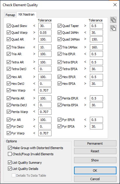
What I like about Siemens Femap pre-processing software, the Element Quality limits are automatically presented to check which elements violate the limits, and put in a group for easy identification.
.Meshing in Femap is different than meshing in Ansys Mechanical. Femap will create a mesh with elements that fail the element quality check. You can then go in and fix individual elements, such as splitting a failed quad element into two triangles. Ansys Mechanical will not give you a mesh. You have to go back to geometry, and slice it up to get pieces of geometry that it can mesh without creating any failed elements.
-
October 13, 2021 at 2:21 pm
Rameez_ul_Haq
Subscriber.peteroznewman, I mean I only got the limits of the element quality NOT from Ansys itself, but only from the online resources i.e. some presentations, YouTube videos and other forums. But you are correct that even in those resources, it wasn't explicitly mentioned what would be the minimum element quality limit, or skewness limit, or A.R limit etc, below which ANSYS would generate an error and the element would be deemed as if it has failed. Yes, I also agree that the only limit that ANSYS has is the limit below zero for different metrics, which basically means that the element itself has failed. Moreover, I have conducted analyses for 3D Hex dominant elements and some of them had a very low element quality, like 0.02. But the analysis still converged and there were no problems.
I asked you a few weeks ago this question as well, in some other thread I opened, that how does the ANSYS realize that this element quality has become bad enough to generate a high distortion error, if you recall. You mentioned that the ANSYS has some pre-developed codes within it which regularly checks the element quality and other metrics and compare it with a base value and tell if the element has become 'bad'. So I am thinking that the minimum limit that the ANSYS compares against is the zero value, if an element plunges below it, then it has failed.
. -
October 14, 2021 at 5:40 pm
Rameez_ul_Haq
Subscriber.peteroznewman, can you kindly provide your views on this question I asked here:
"I just wanted to make sure that even if I have low quality elements, but the displacements calculated at the nodes by solving the global stiffness matrix equation will still be 'kinda' accurate, right? Its just that the shape functions (while interpolating the displacements within the element, and then stresses from the Guass integration points onto the element) will suffer because of the element's low quality, right? Or since each of the elemental stiffness matrix of an element itself has an influence of the shape functions, so the calculated displacements' accuracy also depends on the elemental quality?"
. -
October 15, 2021 at 11:25 pm
peteroznewman
Subscriber.Rameez_ul_Haq
My view is that you can trust the displacements if all elements pass the warning quality check.
Stress values require a mesh convergence study, which should be done using elements that pass the warning quality check.
.
-
- The topic ‘Effect of Element quality, Aspect Ratio, and Skewness on solution and results?’ is closed to new replies.
-
3597
-
1208
-
1092
-
1068
-
952
© 2025 Copyright ANSYS, Inc. All rights reserved.