I am simulating the capacitance between two conductive plates. The plate-to-plate distance is swept from:
Hmin = 0.0011202 mm
to
Hmax = 4 mm
The geometry, material setup, boundary conditions, and distance sweep are the same in all cases. However, I tested three different automatic mesh configurations and compared the capacitance result:
| Case Study | Mesh Refinement | Dynamic Surface Resolution | TAU Mesh | Hmin | Hmax | Maxwell Result (pF) | Q3D Result (pF) |
|---|
| Case 1 | Maximum | Disabled | Disabled | 0.0011202 mm | 4 mm | 20.16 | 14.96 |
| Case 2 | Maximum | Enabled | Disabled | 0.0011202 mm | 4 mm | 12.25 | 10.04 |
| Case 3 | Maximum | Enabled | Enabled | 0.0011202 mm | 4 mm | 23.18 | 10.00 |
Issue:
The calculated capacitance changes significantly depending on the automatic mesh settings, although the model setup is unchanged. For example, the Maxwell result changes from 12.25 pF to 23.18 pF, while the Q3D result changes from 10.00 pF to 14.96 pF over the same distance range.
Question:
Why do the capacitance results vary so much between these automatic mesh configurations? For capacitance extraction between two conductive plates, which software should I trust more, ANSYS Maxwell or ANSYS Q3D, and which mesh configuration should be considered the most reliable? Also, what is the recommended procedure to verify mesh convergence for this model?
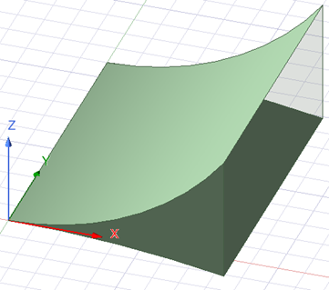 https://drive.google.com/file/d/1UkA5H-PwPPw-MLbwMty-_IaUeAUvFFgo/view?usp=drive_link


















 You are navigating away from the AIS Discovery experience