I’m trying to determine the simplest way to estimate power output from a magnetic power harvester modeled in Ansys Maxwell. The device functions similarly to a current transformer, where a primary conductor carrying AC current induces voltage in a secondary winding connected to a resistive load.
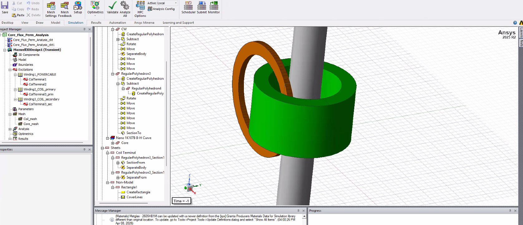
For simplification, the grey cylinder is the conductor, the green cylinder is a magnetic core and the orange loop is the copper winding. I modeled the copper winding as a single-loop representation with defined primary and secondary windings. The conductor is excited with a prescribed AC current (60 Hz), and I am attempting to extract the resulting voltage and current on the coil.
Currently, I've assigned both the primary and secondary as voltage-type windings with 0 V and specified a resistance. However, the simulation results show nearly zero induced voltage and extremely low current on the secondary, so I think the setup might be inaccurate.
Any guidance on the correct/ simple setup for extracting voltage and power would be greatly appreciated.