ZenerDalf
Subscriber
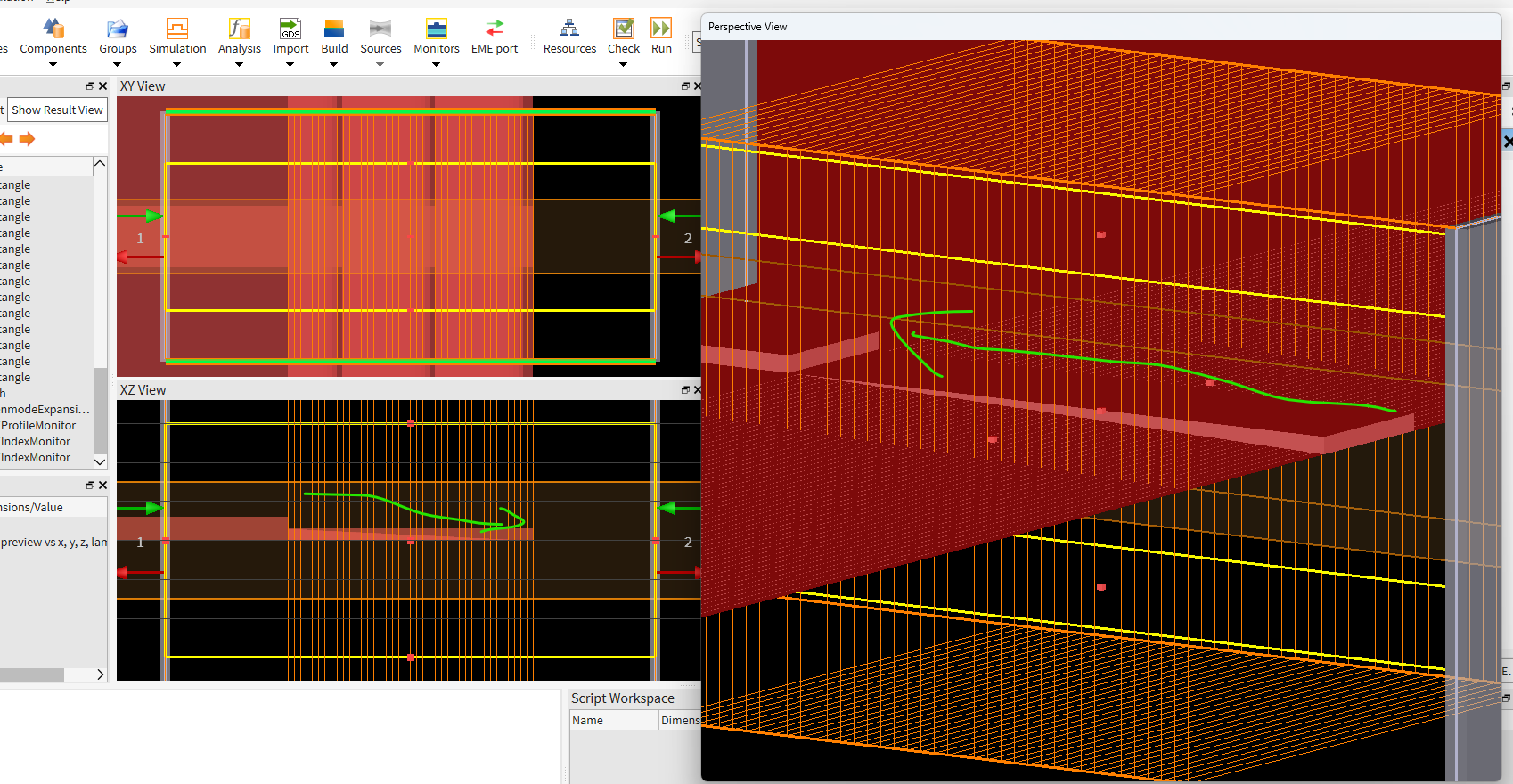
Here is the script code used as reference. Even using Metal or PML boundaries I get full transmission of my fundamental TE mode.
selectall; deleteall; clear; closeall;
for (i=1:401) {
name = "TFLN"+num2str(i);
if (materialexists(name)) { deletematerial(name); }
}
n_TFLN = [2.21; 2.14; 2.21];
temp = addmaterial("Dielectric");
setmaterial(temp, "name","TFLN1");
setmaterial("TFLN1","Anisotropy",1);
setmaterial("TFLN1","Refractive Index",n_TFLN);
TFLN_wg_width=2.5e-6;
TFLN_thick=0.6e-6;
TFLN_rib_h_start=0.3e-6;
TFLN_rib_h_end=0.3e-6;
TFLN_slab_h_start=0.3e-6;
TFLN_slab_h_end=0.0e-6;
L_taper=10e-6;
N1=50;
l_seg=L_taper/N1;
addrect;
set("x min",-20e-6);
set("x max",0);
set("y min",-100e-6);
set("y max",100e-6);
set("z min",0);
set("z max",TFLN_slab_h_start);
set("material", "TFLN1");
set("name","Input Slab");
addrect;
set("x min",-20e-6);
set("x max",0);
set("y min",-TFLN_wg_width/2);
set("y max", TFLN_wg_width/2);
set("z min",TFLN_slab_h_start);
set("z max",TFLN_slab_h_start+TFLN_rib_h_start);
set("material", "TFLN1");
set("name","Input Rib");
addrect;
set("x min",L_taper);
set("x max",L_taper+20e-6);
set("y min",-TFLN_wg_width/2);
set("y max", TFLN_wg_width/2);
set("z min",TFLN_slab_h_end);
set("z max",TFLN_rib_h_end);
set("material", "TFLN1");
set("name","Output");
slab_start=TFLN_slab_h_start;
slab_end=TFLN_slab_h_end;
rib_h=TFLN_rib_h_start;
d_slab=(slab_start-slab_end)/(N1-1);
for (i=1:N1) {
slab_i=slab_start-d_slab*(i-1);
if (slab_i<0) { slab_i=0;}
x1=l_seg*(i-1);
x2=l_seg*i;
#slab going to 0
addrect;
set("name","Slab_taper_"+num2str(i));
set("x min",x1);
#set("x min",0);
set("x max",x2);
set("y min",-100e-6);
set("y max",100e-6);
set("z min",0);
set("z max",slab_i);
set("material","TFLN1");
addrect;
set("name","Rib_taper_"+num2str(i));
set("x min",x1);
#set("x min",0);
set("x max",x2);
set("y min",-TFLN_wg_width/2);
set("y max",TFLN_wg_width/2);
set("z min",slab_i);
set("z max",slab_i + rib_h);
set("material","TFLN1");
}
addmesh;
set("x min",-10e-6);
set("x max",L_taper+10e-6);
set("y min",-1.5e-6);
set("y max",1.5e-6);
set("z min",-1.5e-6);
set("z max",1.5e-6);
set("dy",10e-9);
set("dz",10e-9);
addeme;
# --- EME span ---
set("x min",-5e-6);
set("y min",-5e-6);
set("y max",5e-6);
set("z min",-5e-6);
set("z max",5e-6);
set("number of cell groups",3);
set("group spans",[5e-6; L_taper; 5e-6]);
set("cells",[1; 40; 1]);
set("subcell method",[0;1;0]);
set("number of modes for all cell groups",20);
set("index",1.45);
set("wavelength",1.55e-6);
set("define y mesh by","maximum mesh step");
set("define z mesh by","maximum mesh step");
set("dy",200e-9);
set("dz",200e-9);
set("y min bc","METAL");
set("y max bc","METAL");
set("z min bc","METAL");
set("z max bc","METAL");
set("display cells",1);
### Setting up Port 1 ###
select("EME::Ports::port_1");
set("use full simulation span",1);
set("port location",'left');
set("mode selection","fundamental TE mode");
### Setting up Port 2 ###
select("EME::Ports::port_2");
set("port location",'right');
set("use full simulation span",1);
set("mode selection","fundamental TE mode");
addemeprofile;
set("monitor type","3D");
set("x min",-5e-6);
set("x max",L_taper+5e-6);
set("y min",-3e-6);
set("y max",3e-6);
set("z min",-3e-6);
set("z max",3e-6);
addemeindex;
set("monitor type","3D");
set("x min",-5e-6);
set("x max",L_taper+5e-6);
set("y min",-3e-6);
set("y max",3e-6);
set("z min",-3e-6);
set("z max",3e-6);