Fluids

Fluids

Topics related to Fluent, CFX, Turbogrid and more.

Surface Reaction Rates Much Lower Than Expected

    • abtharpe42
      Subscriber
      I am trying to simulate ammonia decomposition through a channel 4 mm in diameter and 1 m long. The walls of the first 10 cm are set to 300 K, the next 60 cm are set to an elevated temperature that I am varying, and the last 30 cm are also set to 300K. The inlet flow is an ideal gas 1:1 molar mixture of NH3 and N2. The velocity inlet is set to a value such that the average velocity through the hot section is about 7.7 cm/s (what was done in the paper linked later) so the turbulence model was set to laminar. The operating pressure is set to 101325. I have a gas-phase reaction, and I have two sets of surface reactions for different materials (ruthenium for one and stainless steel for the other) to compare against each other. The surface reactions are applied to the hot walls only. The domain is 2D axisymmetric. The gas-phase and stainless steel surface reactions and the channel geometry are from a paper with the DOI: https://doi.org/10.1016/j.ijhydene.2023.04.106 while the ruthenium reaction was given to me by a colleague. The mechanisms are given below where the units for the pre-exponential factor are given in cm, mol, and s where applicable:
       
      Gas-Phase Mechanism (r_g=k*C_nh3):
       
      ELEMENTS
      H N Ni
      END
       
      SPECIES
      H2 N2 NH3 
      END
       
      REACTIONS KJOULES/MOLE
      NH3 => 1.5H2 + 0.5N2 1.01E7 0.0 240
      END
       
       
      Surface Mechanism for Stainless Steel (r_s=k_s*C_nh3):
       
      MATERIAL NI_CATALYST
      SITE/Ni_SURFACE/    SDEN/0.1/
      Ni(S)
      END
       
      THERMO
      300.0  3000.0  1000.0
      Ni(S)                   Ni  1               S    300.0    3000.0  1000.0       1
      0.00000000E+00 0.00000000E+00 0.00000000E+00 0.00000000E+00 0.00000000E+00    2
      0.00000000E+00 0.00000000E+00 0.00000000E+00 0.00000000E+00 0.00000000E+00    3
      0.00000000E+00 0.00000000E+00 0.00000000E+00 0.00000000E+00                   4
      END
       
      REACTION KJOULES/MOLE MWOFF              
      NH3 => 1.5H2 + 0.5N2     3.1E5  0.0  116
      END
       
       
      Surface Mechanism for Ruthenium (r_s=k_s*C_nh3*C_ru):
       
      MATERIAL CATALYST
      SITE/Ru_SURFACE/    SDEN/1.66E-9/
      Ru(S)
      END
       
      THERMO
      Ru(S)                   Ru  1               S    300.0    3000.0  1000.0       1
      0.00000000E+00 0.00000000E+00 0.00000000E+00 0.00000000E+00 0.00000000E+00    2
      0.00000000E+00 0.00000000E+00 0.00000000E+00 0.00000000E+00 0.00000000E+00    3
      0.00000000E+00 0.00000000E+00 0.00000000E+00 0.00000000E+00                   4
      END
       
      REACTIONS        KJOULES/MOLE   MWOFF              
      NH3 + Ru(S) => 1.5H2 + 0.5N2 + Ru(S)    1.5E16  0.0  128.0
      END
       
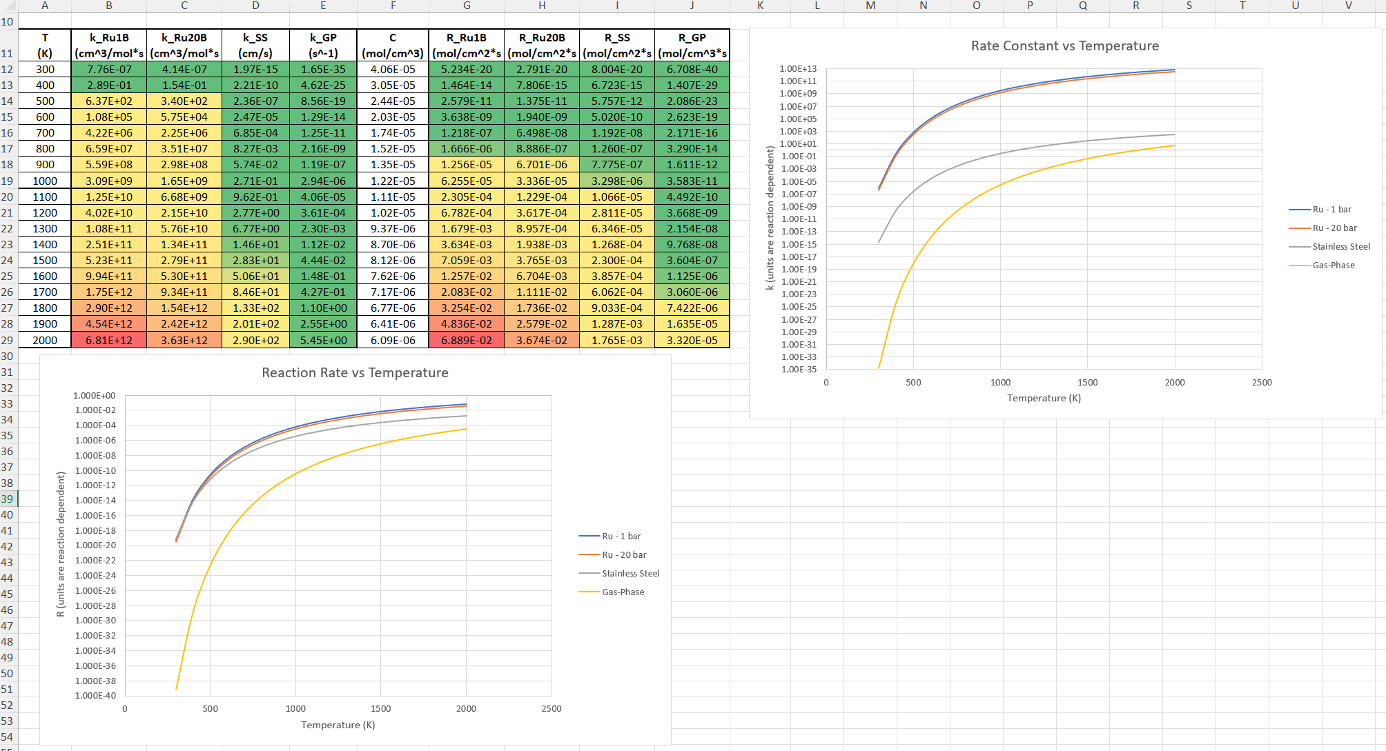
      Here is a screenshot of my Excel charts showing how rate constant and reaction rate compare with temperature when the pressure is 101325 Pa:
       
       
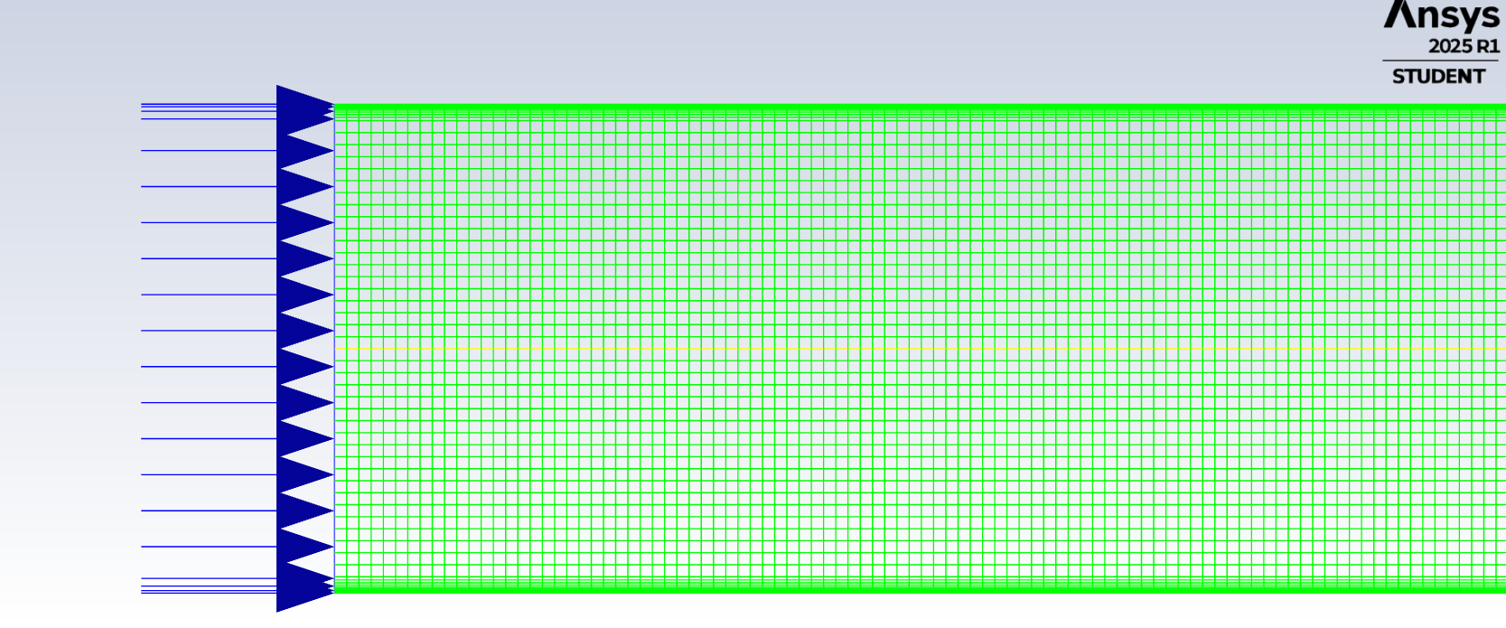
      A piece of the mesh towards the inlet is shown below:
       
       
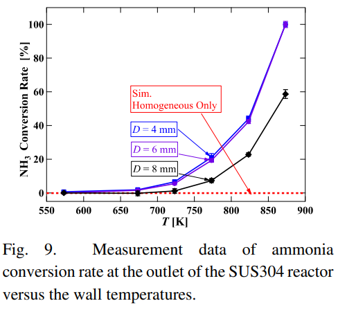
      This is the chart from paper that I am trying to follow (they used Cantera for their simulations):
       
       
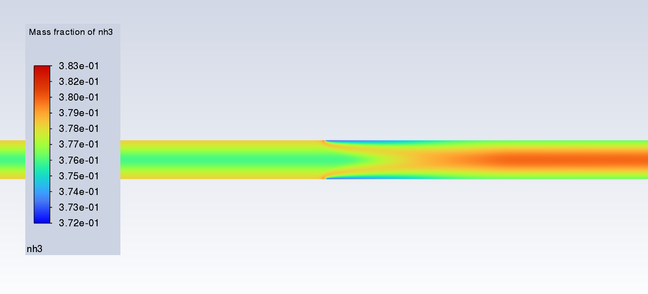
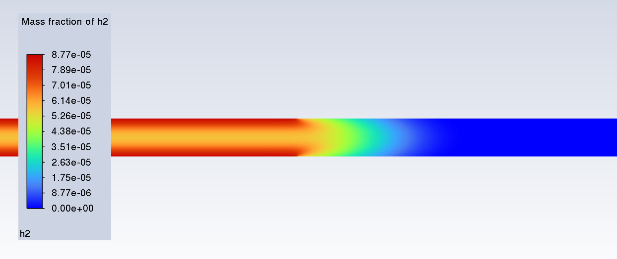
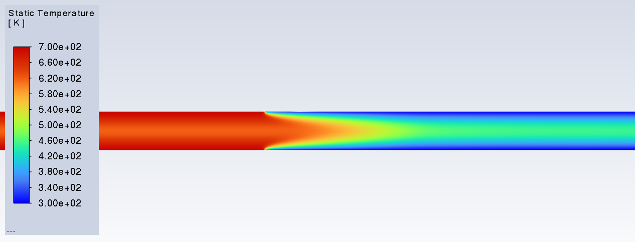
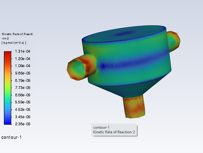
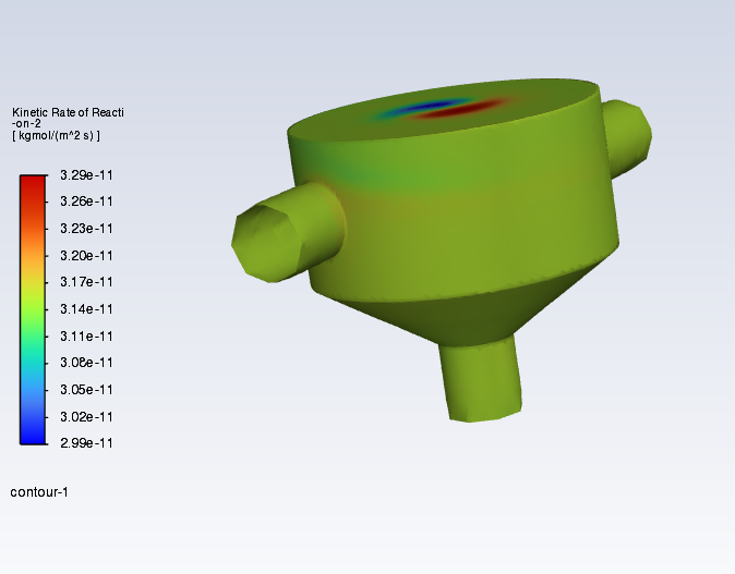
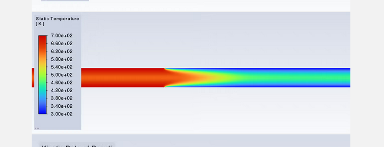
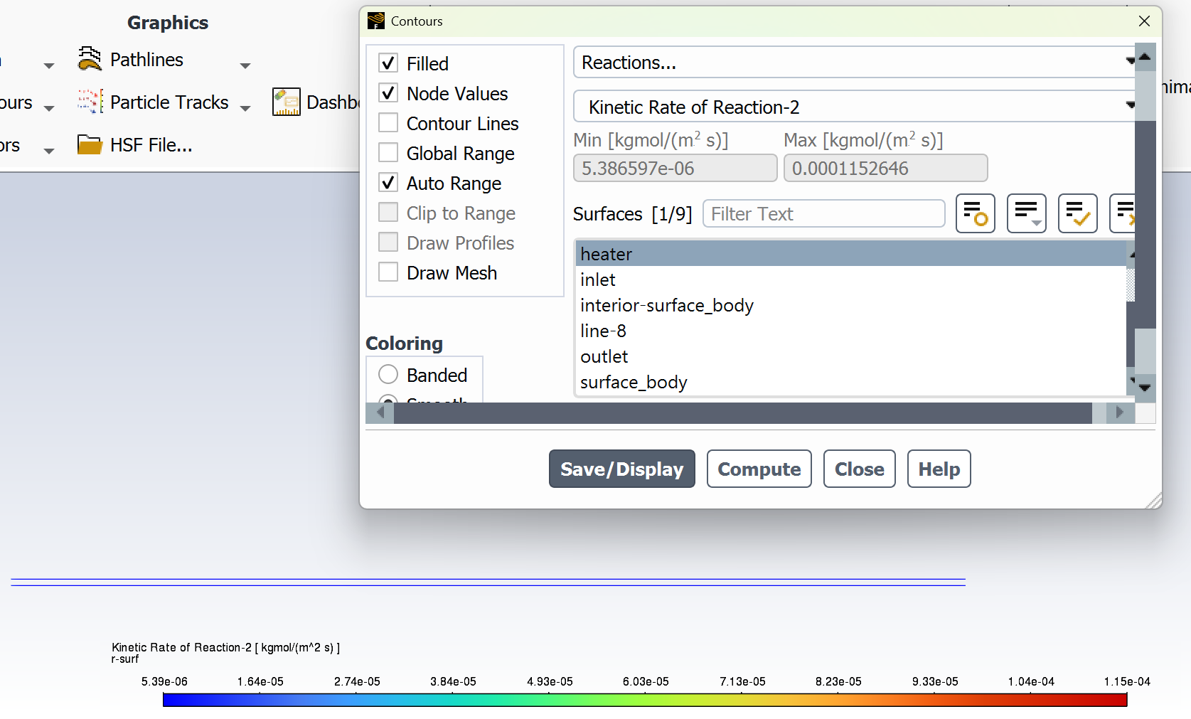
      The following contours, towards the end of the hot zone, are from a prematurely paused simulation when the hot walls are set to 700 K with the stainless steel catalyst enabled, which should cause a considerable surface reaction rate for both catalysts: 
       
       
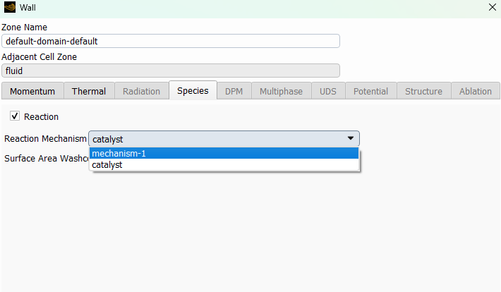
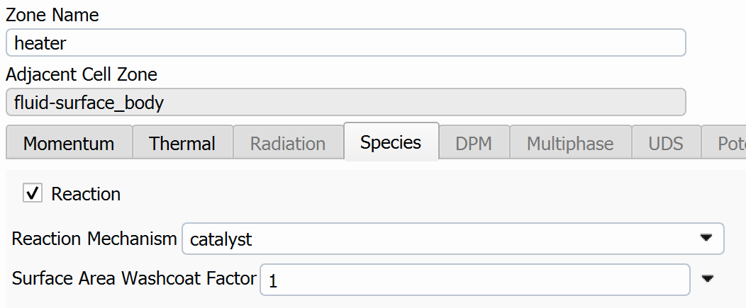
      As can be seen from the H2 mass fraction and surface reaction results, there is basically no surface reaction happening for either mechanism, even when I go up to 1000 K. For the ruthenium catalyst mechanism, I never had a problem up until this point until fairly recently. All I did recently was clean up the text files to make them easier on the eyes, and this is my first time using the stainless steel mechanism. There are no import errors for the mechanism, and the values of the kinetic parameters as they appear in the Reactions window in are good. Any help I can get would be greatly appreciated.


    • SamW
      Ansys Employee

      To clarify - you were seeing hydrogen production in the same simulations before changing your mechanism for the Ruthenium simulations? Or is this the behavior you've been seeing all along?

      If the Arrhenius parameters look good in Fluent, my first thought would be to check the species tab for your wall boundary. Do you have the reaction/species info set up the way you want there?

    • abtharpe42
      Subscriber

      Neither the stainless steel or ruthenium mechanisms are working with this specific simulation in that I am getting next to no H2 production with a wall temp of 1000 K. The only thing I do to enable the surface reaction on a wall BC is to check the Reaction box and select my catalyst in the dropdown menu. I've done a few FR/No TCI simulations with the ruthenium chemistry before and they've worked pretty well, albeit with pretty slow convergence. Yesterday I went back to an older 2D planar simulation that I've done with a turbulent NH3 flow traversing rows of circular pins (or circular cut-outs in the 2D plane), the edges of which were set to a constant temperature and had the surface reactions applied. At the time was testing to see how well the EDC-PaSR model works with surface reactions (it does work and way faster than FR/No TCI) since I was going to couple them to a combustion simulation of a gas turbine combustor that I'm working on. I retried that simulation from scratch with both the EDC-PaSR and FR/No TCI to see if I screwed something up with the ruthenium mechanism (haven't tried the stainless steel yet), and I did absolutely nothing different from before with the BCs. Lo-and-behold the simulation with the pins worked with both chemistry models. For whatever reason, it's this paper's scenario specifically that is not working at all.

    • abtharpe42
      Subscriber

      For example with FR/No TCI with 1000 K walls:

    • jcooper
      Ansys Employee


      Hi: 

      I took your mechanism and loaded it up on a dummy case here. The first pothole can come up if you forget to set the wall mechanism to catalyst.  (It seems like you have done that, though, because your rates are small, but not totally zeroed.)


      Next we can look at boundary conditions. You mentioned you had set temperatures of up to 1000K:  Since the surface reaction uses wall temperature, increasing the gas temperature may have no impact if a low wall temperature is set.

      Here are my reaction rates for 1000 K wall temperature (300 K gas temperature):


      And for 300 K wall temperature with 1000 K gas temperature:

      So it seems there is something special about your scenario

      Regards,

      Judy


    • jcooper
      Ansys Employee


      In this image, I am not seeing any signs of low wall temperatures upstream and high wall temperatures on the upstream… Is it possible that you have the boundary conditions reversed?


    • SamW
      Ansys Employee

      In addition to Judy's suggestions, if the same setup works for a turbulent case but not the small-channel laminar one, it suggests the possibility of a diffusion-limited process. I wouldn't expect the impact to be quite that large, but you could try selecting the "Full Multicomponent Diffusion" option in the species dialog to see what effect it has, if any.

    • abtharpe42
      Subscriber

      I've gone back to my paper's scenario to double check to see if I screwed up the setup. Everything looks good. I had the simulation run overnight to see if I just wasn't giving it enough iterations, and I've just now seen how weird this thing is behaving. Here are some contours from the paper's scenerio, even though they're kinda hard to see because the geometry is a very thin and long pipe:


    • abtharpe42
      Subscriber

      It looks like the H2 is disappearing after the hot zone, which is crazy because there are no backwards reactions involved at all. Here is my species transport window:

    • jcooper
      Ansys Employee

      What happens to your solution if you set Chemistry solver to Direct Source ? Does anything change? I wonder if the competing, essentially duplicate reactions (w.r.t species) are causing problems for the source linearizations imposed by Chemkin CFD... It may also be tricky for the numerics to deal with the sudden shift in wall temperature..  Are you doing anything with the mesh, like refining in the axial direction, to help the solver cope with this?


    • abtharpe42
      Subscriber

      I'm currently rerunning the simulation with Direct Source, so it'll take some time to see the complete results, although right now it looks like it's gonna be the same song-and-dance as before based off my NH3 conversion report plot still hovering around 0% or even slightly negative. As far as the mesh goes, it's basically uniform quad cells 0.1 mm in size with inflation layers on the wall, so a little over 200k cells total. The convergence with this simulation has always been really good too, even down to 1e-6.

    • jcooper
      Ansys Employee


      I wonder if the uniform mesh is the problem...  It looks like there are some pretty steep gradients where the wall temperature increases, with almost a discontinuity in the behaviour there.  If your previous successful tests all have uniform wall temperatures, I would look at this aspect.

      You may need to bunch the mesh going in to and out from this transition point.

      Regards,

      Judy


    • abtharpe42
      Subscriber

      I'll take a look at that tonight and then I'll post an update later when I get the chance.

    • abtharpe42
      Subscriber

      Using the Direct Source chemistry didn't really change anything. I also enabled AMR to adapt the mesh to the temperature gradient because 2025 R1 still gives me a cortex error and crashes Fluent when I change a mesh in the Mesh block (Fluent Meshing too) and then update the connected Setup block when I had the Chemkin-CFD solver enabled before the mesh change. Refining the mesh around the temperature gradient didn't fix anything either. So I'm still at a loss with this case. 

Viewing 13 reply threads
  • You must be logged in to reply to this topic.