-
-
June 2, 2020 at 12:12 pm
CFDGer
SubscriberHello,
I am trying to simulate the airflow around a 2D-wedge which is moving at hypersonic speed (Mach=8 at 30000 m).
I understand and have read that for my application pressure inlet, pressure outlet and pressure farfield boundary conditions are applicable.
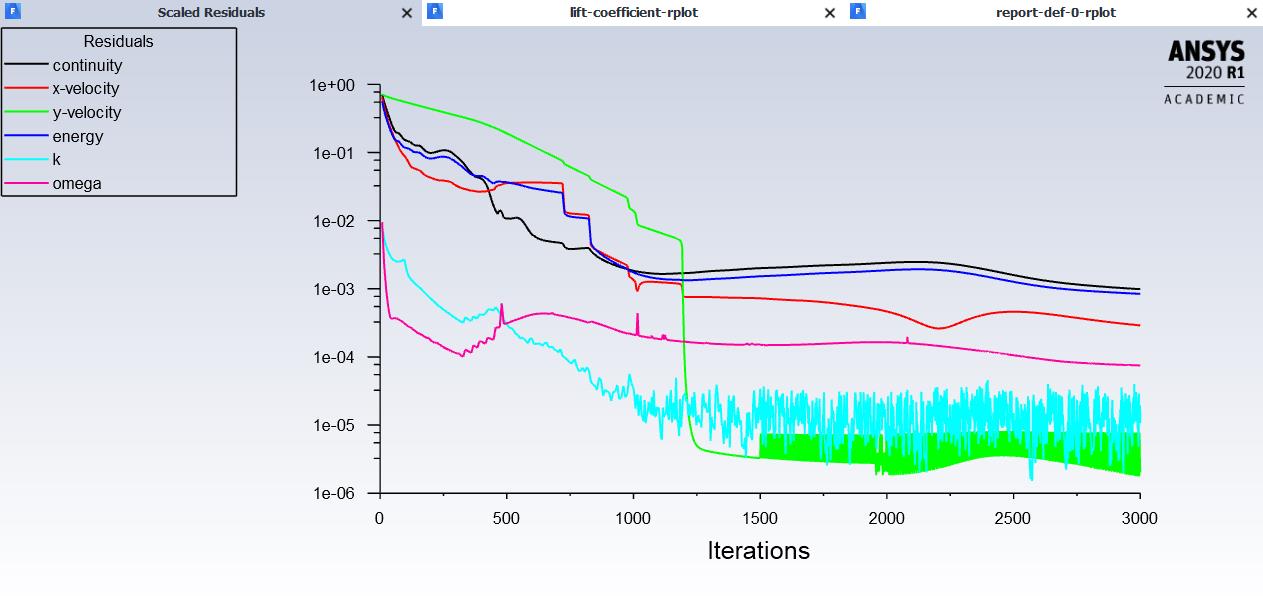
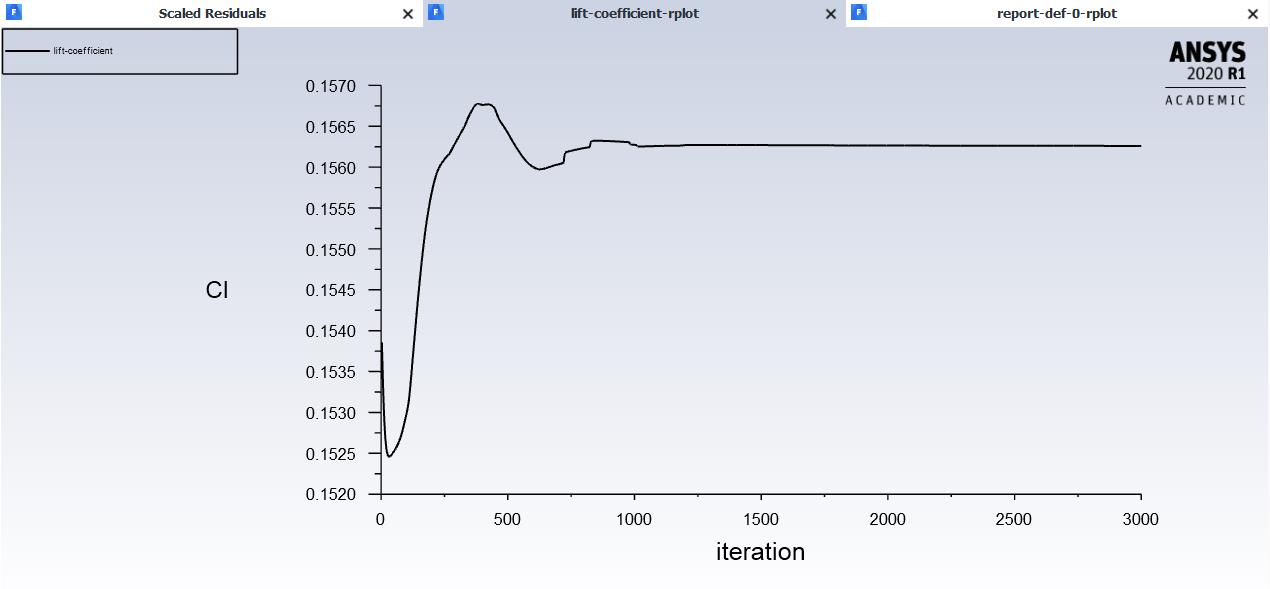
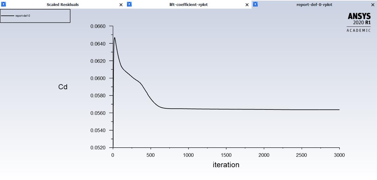
My problem is that my solution won't converge at all. I have tried changing the boundary conditions and the solution methods, switching on and off the turbulence modeling and so on.
Here are my settings:
Density based
Energy on
Viscous k-omega
Fluid: Air: Density ideal-gas and viscosity according to sutherland law
Boundary Conditions:
Inlet: Pressure inlet: I calculated a total pressure of p(total) = 2.93e8 Pa (isentropic relation with Ratio of Specific Heats = 1.4, Ma=8 and p(static, 30000 m, ISA)=301hPa. I set the "Gauge Total Pressure" to my calculated total pressure value. The "Supersonic/Initial Gauge Presse" I set to my p(static). The temperature is 228.75 K (ISA, 30000 m)
Outlet: Pressure outlet: Here I set the "Gauge Pressure" to the aforementioned p(static) = 301hPa and the Temperature to 228.75 K.
The outer "walls" defined as pressure far field BoC: Ma = 8 and Gauge pressure to p(static) = 301hPa.
I also set the "Operating Pressure" to 0.
Solution Methods:
Implicit, Roe-FDS, Gradient: Least Squares, Flow, Turbulent Kinetic Energy and Specifiy Dissipation Rate: Second Order Upwind
Now first of all as I mentioned the solution doesn't converge at all. Then when I check the Reference Values, I see that the calculated velocity in the inlet doesn't represent the numbers I would have expected.
I would be very thankful if you could help me find the solution for my problem. I am new to CFD/Ansys which is why I want to gain as much knowledge as possible.
Thank you very much.
-
June 2, 2020 at 1:32 pm
Kalyan Goparaju
Ansys EmployeeHello,
A couple of things
1. Reference values are values you set. Can you please elaborate on 'I see that the calculated velocity in the inlet doesn't represent the numbers I would have expected.'
2. Did you try starting with first order schemes and letting the solution settle before switching over to second order?
Here is a link to a supersonic flow over a 2D wedge problem. Though it's not hypersonic, I would recommend following similar setup procedure, except for the turbulence model (they use Laminar. You can use your choice of turbulence modeling).
https://confluence.cornell.edu/display/SIMULATION/FLUENT+-+Supersonic+Flow+Over+a+Wedge
Thanks,
Kalyan
-
June 2, 2020 at 4:01 pm
CFDGer
SubscriberHello Kalyan,
thank you very much for your reply.
1. The reference values computed from the inlet show a different (much lower) velocity than I thought it should have shown (Ma=8, -> v=2425 m/s, but the computed velocity value is something like 600 m/s. Maybe I misunderstand the meaning of this value.).
2. This is something I will try, thank you.
Ok it worked but I had to remesh. The problem apparently was/is the bias I chose for the mesh near my wedge to get a finer resolution near the wedge surface at the boundary layer. I also changed all boundary conditions surrounding the flowfield to one pressure farfield boundary condition. In this way the computed velocity under "Reference Values" was correct.
I now don't understand why a refinement of the mesh at the boundary layer caused such a problem and how I should approach this problem.
Do you have any further suggestions on that?
Thank you very much for your support.
Best regards
-
June 3, 2020 at 3:28 am
Kalyan Goparaju
Ansys EmployeeHello,
Resolution of boundary layer is extremely critical to getting accurate results, especially in high speed compressible flows. In this flow regime, it is generally recommended to not use wall functions, but instead have fine enough resolution to integrate through the viscous sub-layer. The minimum recommended resolution is y+<1 and 10-15 points within the BL. However, it doesn't hurt to pack in more cells to capture the gradients with high fidelity.
Please mark the appropriate answer as 'Is Solution' so that it can help others.
Thanks,
Kalyan
-
June 3, 2020 at 9:50 am
CFDGer
SubscriberHello Kalyan,
thanks for the clear explanation. I understand the theory you explained but as soon as I implement the y which is needed for my y+<1 the solution doesn't converge anymore. Further the temperature is limited to 1.000e0 and 5.0000e03 in quiet a few cells. Additionally the turbulent viscosity is lmited to a viscosity ratio of 1.000e5 in many cells.
Do you or anybode else maybe have an axplanation for this or an idea on how I can solve this?
Thanks!
-
June 3, 2020 at 10:50 am
Rob
Forum ModeratorTypically it's mesh or settings related. For the former, have you got enough resolution to pick up the streamwise flow gradients and are the cells good quality? For the latter, you need to check the inlet/outlet ect are correct and sufficiently far from the area of interest.
-
June 3, 2020 at 11:17 am
CFDGer
SubscriberHi rwoolhou,
I have calculated an y(distance wall to node)=5.1e-7m and therefore the height of my first cell to my understanding is yh=2*y=1e-6m. I attached two imagesof my mesh. I can't say if I have enough resolution to pick up the streamwise flow gradients. The angles of my cells are >27°, the aspect ratio is very very big due to the resolution near the boundary layer. I also can't say if the boundaries are far enough away from my area of interest.
I hope this information is informative in order to understand my problem.
-
June 3, 2020 at 12:45 pm
Kalyan Goparaju
Ansys EmployeeThere is too much of a jump between fine region around the wedge and the 'far-field'. I would strongly recommend creating a smoother transition between the different regions.
-
June 4, 2020 at 10:47 am
Rob
Forum ModeratorYou also need to review the mesh aspect ratio. Have a look in the tutorials and/or online to see how the aerofoil examples are meshed.
-
June 9, 2020 at 1:34 pm
CFDGer
SubscriberThanks for the replies. Refining the mesh further helped to get a converged solution. It converges unfortunately only at 1e-3 so I think additional refinement needs to be done.
-
June 9, 2020 at 2:44 pm
Rob
Forum ModeratorPut some monitor points in too, you may find you also pick up transients in the solution, ie the "steady" flow isn't quite steady.
-
June 10, 2020 at 1:06 pm
CFDGer
SubscriberThank you for your reply! Which parameters do I have to look at to figure out whether I pick up transients in the solution? And which of the options of the "Results" Tab in Fluent is best suited for displaying those parameters? Also, where is the smartest location to place those monitor points? So far I have only placed lines prependicular to the surface in order to get velocity and temperature profiles.
Thanks for your support.
-
June 10, 2020 at 1:22 pm
Kalyan Goparaju
Ansys EmployeeHello,
1e-3 is a good convergence criteria to have met, however, as Rob suggested, please ensure that the variables also indicate a steady state flow.
You could perhaps use lift and drag force report definitions on the body as monitors. You can create Report definitions from the Solution -> Reports -> Definitions -> New -> Force Report ->Drag/Lift. Once you set these up and run the simulation, these values will be tracked over time and plotted (ensure that while creating report definitions, Report Plot option is checked).
Thanks,
Kalyan
-
June 10, 2020 at 1:46 pm
-
- The topic ‘Boundary Layer Setup Compressible hypersonic flow’ is closed to new replies.
-
6570
-
1906
-
1463
-
1311
-
1022
© 2026 Copyright ANSYS, Inc. All rights reserved.


