-
-
August 18, 2025 at 3:42 pm
oelgarhy
SubscriberI have been trying to simulate current going through a busbar to test a fusible link; I will attach a picture of the model below. The way I've tested it is creating a mesh, doing the geometry, adding convection, setting material as nickel and such, then putting 50A of current to each of the 3 links individually, and then 0V to the other 3 terminals. I ran into a problem where the full current is being dumped into the first ground terminal instead of being equipotential. I am trying to simulate 3P cells' positive terminals discharging in series with another 3P cells' negative terminals. How do I simulate this without having it dump all 150A into the first terminal and having a very skewed temperature reading? I have done everything correctly on the mechanical side I believe as I reached out to a mechanical engineer who was pretty good at ansys, I am stuck on the electrical portion as I have no idea how to make it realistic discharge instead of causing it all to go into one terminal.
-
August 19, 2025 at 4:07 pm
dlooman
Ansys EmployeeThat appears to be a physically correct solution. If there is some un-modeled constraint that produces an equal current at each ground you could couple the volt dof at the entrance to the three ground terminals.
-
August 19, 2025 at 4:27 pm
oelgarhy
SubscriberI think it's correct for some simulations but not this one, this connects 3P cells' positive terminals to A different 3P cells in series' negative terminals. That means it gets 50A from each parallel positive and discharges 150A into the negative parallel terminal block, discharging 50A into each negative terminal. The picture I sent shows the simulation if it dumped the entire 150A into only the first negative terminal, so if I model the current density it would show it at each of the positive fusible links, but only the first negative fusible link.
-
-
August 19, 2025 at 4:40 pm
dlooman
Ansys EmployeeAnother idea is to apply the assumed 50 amp current to each of the negative terminals. Volt still needs to be constrained somewhere in the model.
-
August 19, 2025 at 4:42 pm
oelgarhy
SubscriberSorry I am unsure what this means. I'm trying to simulate it to show when the fusible links would melt when current flows through; I cannot get an accurate representation if all the current only goes into one terminal and ignores the other two grounds. I am very new to ansys as we do not use it much at all in Electrical Engineering courses(I am a junior) so I may need guidance in what you specifically mean, thank you!
-
-
August 19, 2025 at 5:00 pm
dlooman
Ansys EmployeeIf your drawing is representative, that's what would happen in real life. The current will follow the path of least resistance.
-
August 19, 2025 at 5:55 pm
oelgarhy
SubscriberI appreciate the responses and your help, but I believe you are mistaken. It’s a parallel connection, if it’s 150A total flowing through a parallel connection, yes the third “ground” has more resistance, but kirkhoff and ohms law state that in a parallel conenction, it should split. yes it may not be equal since the first terminal may get more while the 3rd terminal encounters more resistance thus having slightly less, but one ground would not get the full 150A if I'm not mistaken.
Correct me if I am wrong as I am only a student, but this is the parallel circuit logic I was always taught.
I will do more research on this though taking what you said into account and see what I come up with, thank you!
-
-
August 19, 2025 at 9:20 pm
mjmiddle
Ansys EmployeeThe terms parallel and series connections are idealized meaning perfectly connected where there are conductors, so zero resistance to those conductors. Here you are modeling what happens inside that conductor as non-perfect. There is a resistivity in the material properties. The entire model being considered together, it cannot be said this is a series or parallel connection. It has elements of both. Even if this were all considered one connection in some series/parallel diagram, so zero resistance, it's would be all one connection, so one node in that diagram; it still can't be called a series or parallel connection.
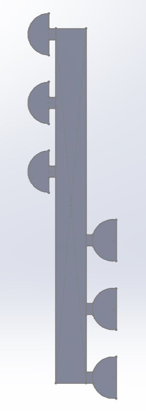
What are your inputs? Did you apply 50 A to each of the knobs at one side? That's probably not realistic, since the voltages would need to be different on each one to meet that 50A prescription on each one. It seems more realistic to apply a common voltage to each of the 3, but the voltage drop to the other 3 will change also from the different current due to the different resistances, so maybe that's not any better.
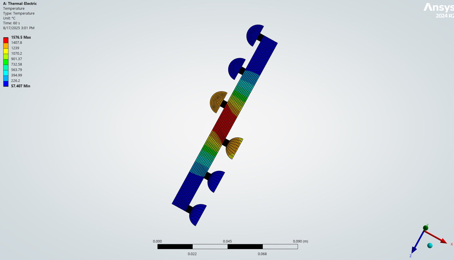
The real issue is that you are analyzing what happens inside a material with resistivity, not a perfect connection that could be called parallel or serial.
-
- You must be logged in to reply to this topic.
-
3717
-
1313
-
1163
-
1090
-
1014
© 2025 Copyright ANSYS, Inc. All rights reserved.