Ansys Assistant will be unavailable on the Learning Forum starting January 30. An upgraded version is coming soon. We apologize for any inconvenience and appreciate your patience. Stay tuned for updates.
Photonics

Photonics

Topics related to Lumerical and more.

Lumerical Charge Matrices for current

    • R.S.Pokharia
      Subscriber

      Hi Everyone

      Hope you all are doing good. 

      I am facing an issue with the size of matrices and hence the result while doing a lumerical charge simulation. It would be great if someone could explain to me the following (it's after I define a dc voltage sweep - total 26 points, on one of my electrodes out of three electrodes and I perform a ssac - AC analysis - total of 20 frequency sweep points, and then use the command "run Charge" in the lumerical script:

      1. I would like to know how is dI (or dIp, dIn) calculated in Lumerical charge when the it is run for a p-n junction Si MZM modulator? I mean what’s the order of the matrix and how’s it dependent on the number of electrodes?
       
      2. I have three electrodes. For a simpler case, I am keeping the ac signal on only one electrode, the second electrode is kept at ground (but I intend to use it for differential signalling) and the third electrode is the ground for both the signals, always. I am getting an incomplete dI matrix for my case when I am trying to follow the traveling MZM modulator example by Ansys. I can only see a 2x26 matrix for dI.
       
      3.How does the I = pinch(Result.dI) function work for my case? I can know this if I can know how lumerical Charge calculates the matrices for dI. I see a 26x2 matrix for I in visualize data but I see it's size in the script results window as 26,2,20.
       
      I have been trying to find out the principle of such matrices from the Ansys sources but have been unsuccessful.

      I look forward to some insight into it.
       
      BR,
      Ravi
    • Niki Papachristou
      Forum Moderator

      Hi Ravi,

      Thank you for reaching out to us! May I ask you which exact example are you following from our application gallery? Is it this one: pn junction diode? Also, from where did you pick up this command:  I = pinch(Result.dI) function? Finally, if you can attach any helpful screenshots of you simulation file that would be helpful to understand in more detail your questions. I am currently working on them and I will come back to you as soon as possible.

      Kind Regards,

      Niki

    • R.S.Pokharia
      Subscriber

      Hi Niki

      Thank you for the reply.
      This is the example I am following: https://optics.ansys.com/hc/en-us/articles/360042328774-Traveling-Wave-Mach-Zehnder-Modulator#:~:text=This%20example%20describes%20a%20complete,and%20eye%20diagram%20are%20calculated.

      I am sharing images of the ppt of the issues I am facing. The first 3 images are of the Ansys example that I am following, and the rest are for my device and the issue. The last is the code that I am using following the example of MZM modulator. I would like to understand the working fo the calculations or how they are made and stored, so that I can work on them accordingly with more than two electrodes in my simulations.

      Please let me know if there's anything else required.

       Best Regards,
      Ravi

    • Niki Papachristou
      Forum Moderator

      Hi Ravi,

      Sorry for my late response here, dI (and dIn, dip) is the small signal current due to a small signal ac voltage applied to any electrode (whichever boundary condition was enabled for small signal ac calculation). The dimension will depend on your settings. The last dimension is always the frequency points from the small signal settings in the solver. The one before that is for the small signal source voltage. If you enabled small signal analysis for one contact only then this will have a dimension of 1. If you enable small signal analysis for multiple contacts then it will have dimension greater than one and each one will give you result for applying the small signal voltage to each of the enabled contacts. The other dimensions are for the DC voltage values at which you are running the ac analysis for. E.g., if you select "last" bias point only for the analysis then these will have dimension of 1. If you select "all" bias points and are sweeping the DC voltage on that contact then it will have that many points.

      I hope that was helpful but let me know if you have any additional questions.

      Kind Regards,

      Niki

    • R.S.Pokharia
      Subscriber

      Hi Niki

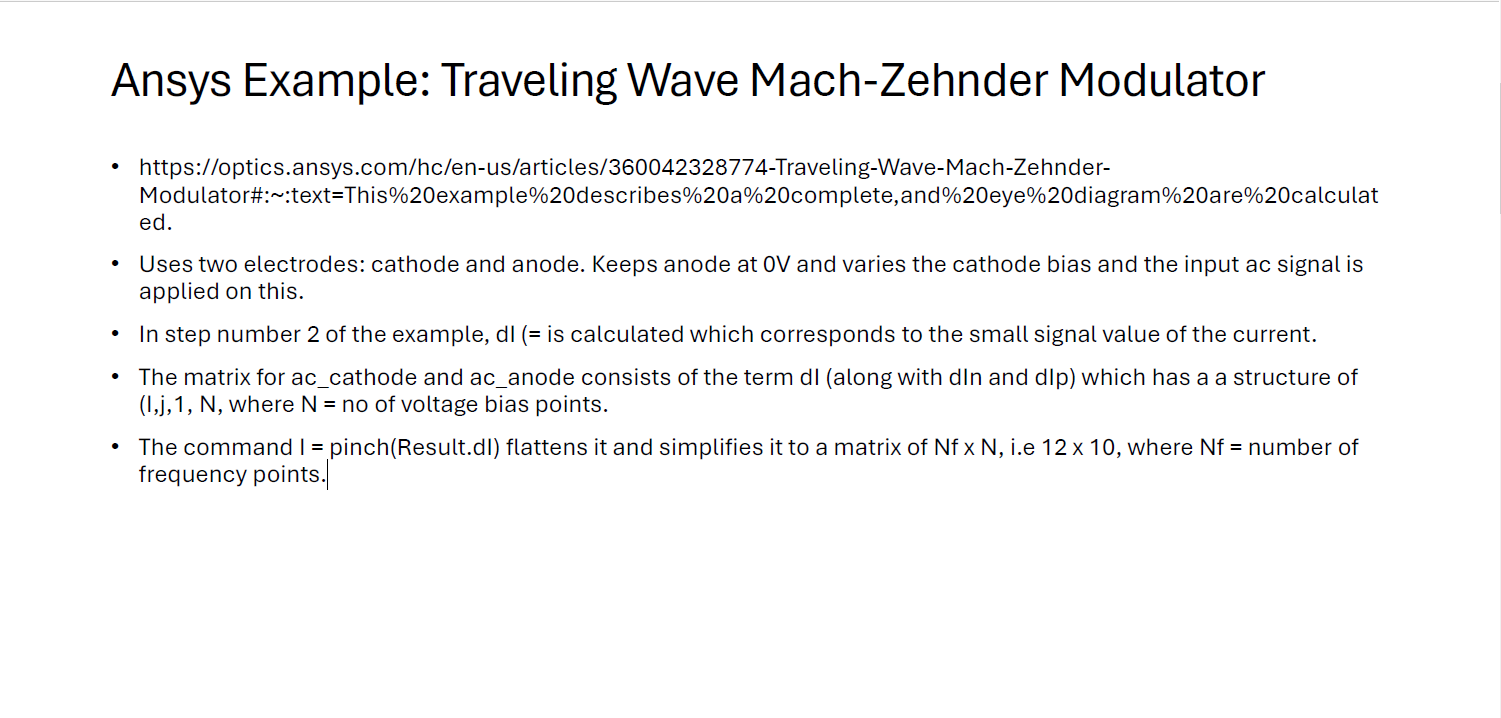
      Apologies for the late response, and thank you for replying. I have been working on understanding the example and trying to design my own device simulation based on that. There are a number of confusions for me still, so I am reaching out to the Ansys Lumerical team for that. Below are my queries for the moment (as of now for the original Ansys example – https://optics.ansys.com/hc/en-us/articles/360042328774-Traveling-Wave-Mach-Zehnder-Modulator#:~:text=This%20example%20describes%20a%20complete,and%20eye%20diagram%20are%20calculated.):
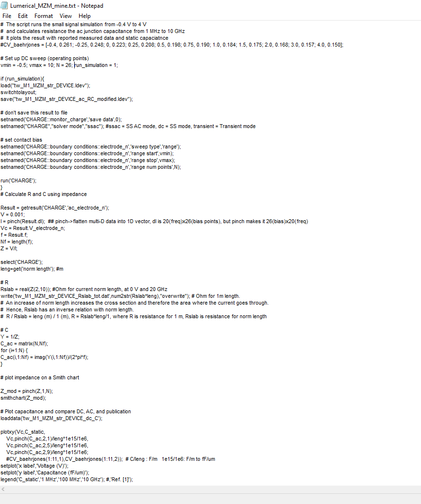
      # set contact bias
      setnamed(‘CHARGE::boundaryconditions::cathode’,’sweeptype’,’range’);
      setnamed(‘CHARGE::boundary conditions::cathode’,’range start’,vmin);
      setnamed(‘CHARGE::boundary conditions::cathode’,’range stop’,vmax);
      setnamed(‘CHARGE::boundary conditions::cathode’,’range num points’,N);

      run(’CHARGE’);}

      Query: When the script runs this, are all the parameters evaluated for all the electrodes?

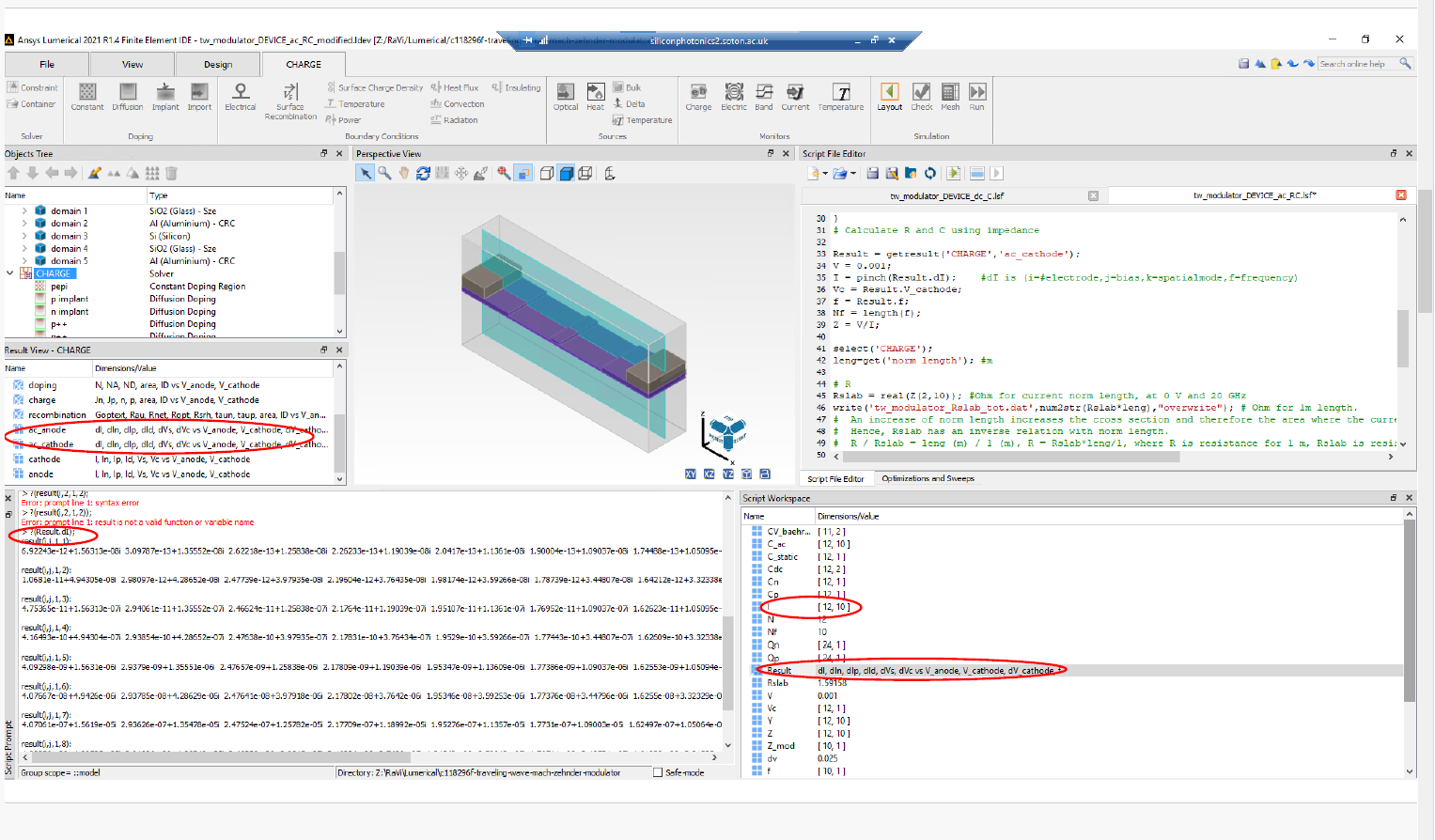
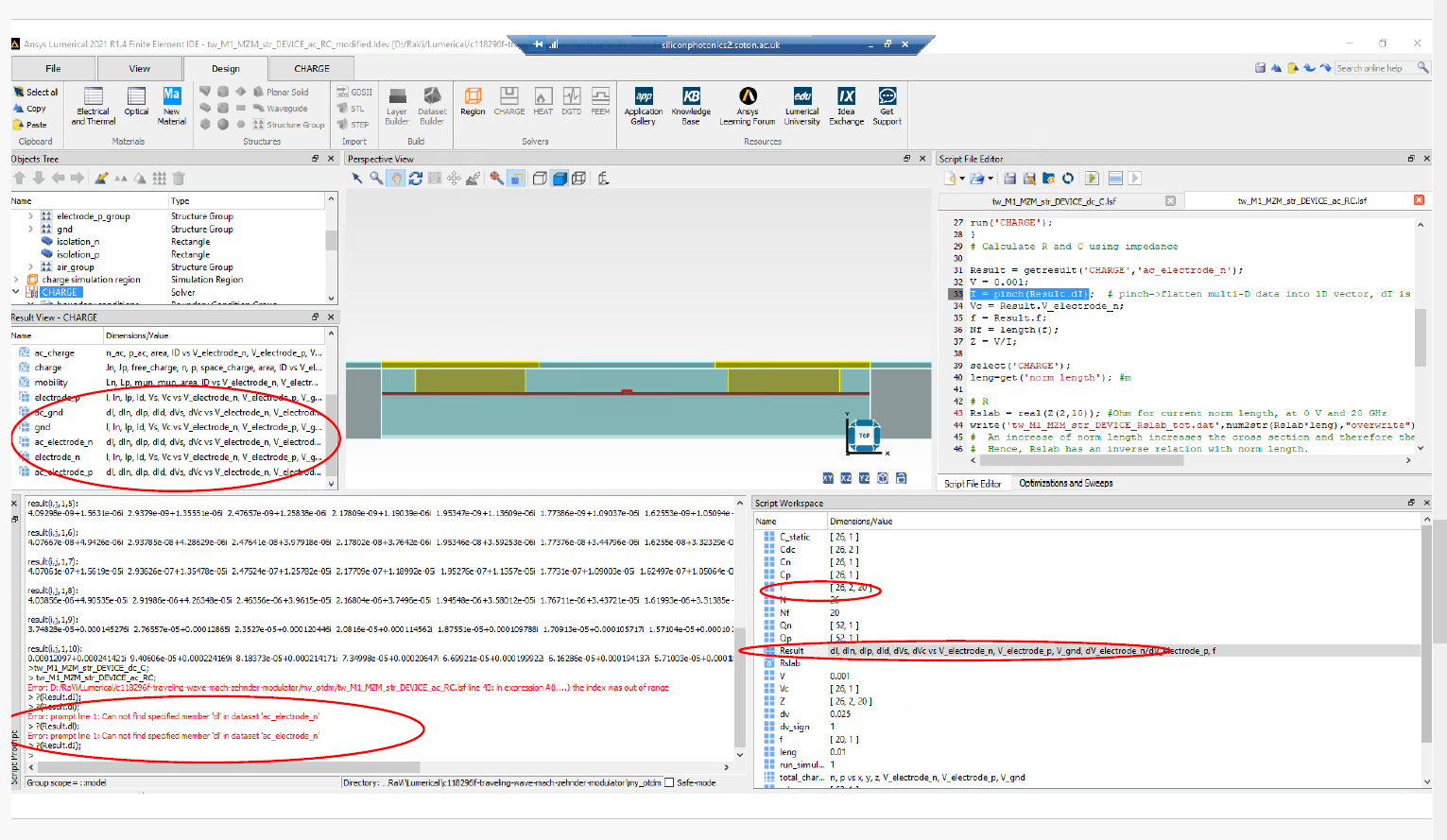
      # Calculate R and C using impedance
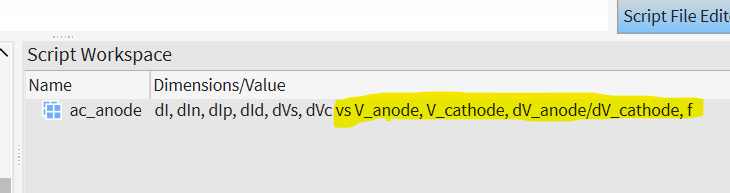
      Result = getresult(’CHARGE’, ‘ac_cathode’);

      V = 0.001;

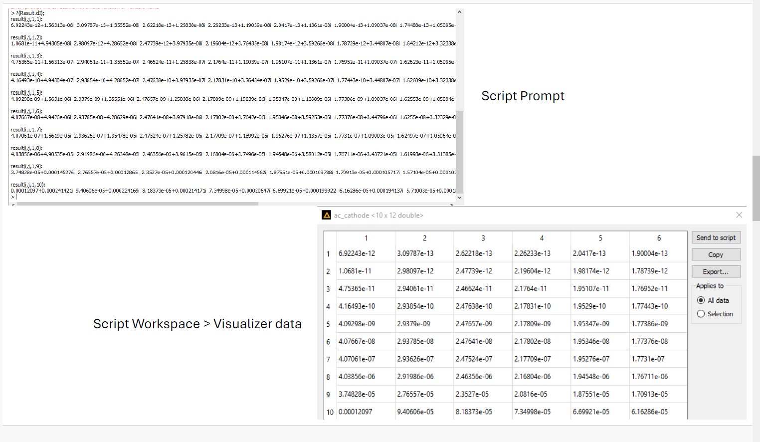
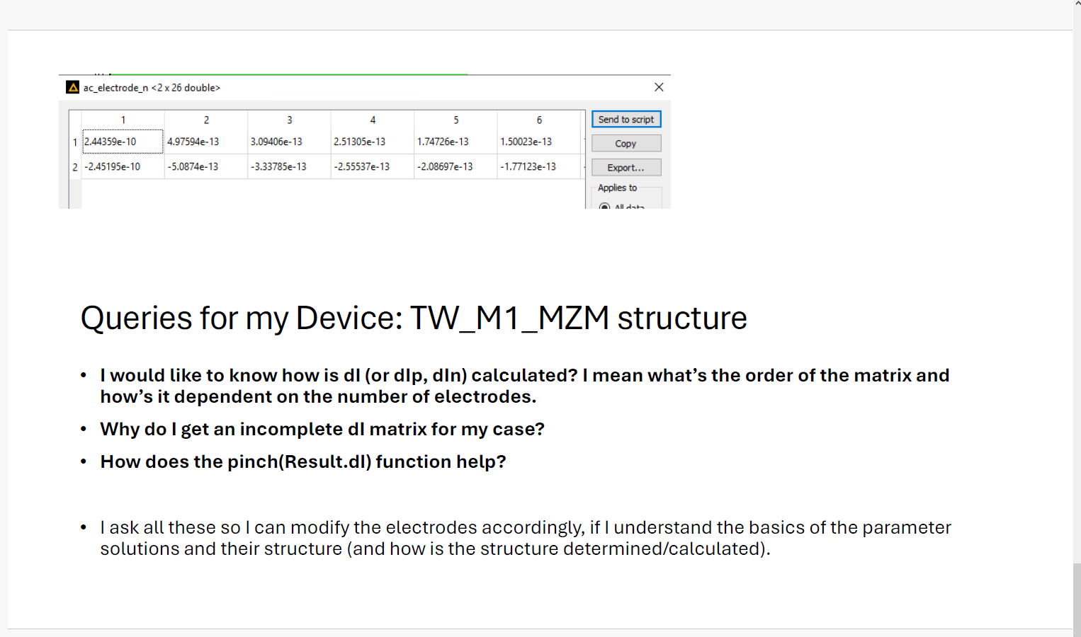
      I = pinch(Result.dI);

      Vc = Result.V_cathode;

      f = Result.f;Nf = length(f);

      Z = V/I;select(’CHARGE’);

      leng=get(‘norm length’); #m

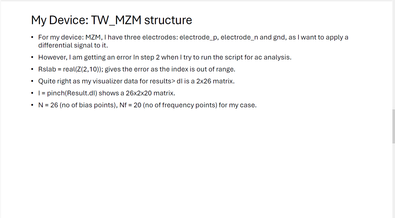
      Query: When the script runs this, the evaluated parameters are extracted for the electrode: cathode i.e. a particular electrode, right? Now, if I have put more than one electrode in my device, say two electrodes, then why does I contain the values pertaining to the other electrode, i.e as you said I has a matrix as (#DC bias index, #electrodes index, #Frequency index)? The result variable has been used to extract the values for one particular electrode, right? I would be (N, 2, Nf) matrix even though it is evaluated for a particular electrode, so should it not be a (N, 1, Nf) matrix always?

      Based on the answers to above, I can proceed ahead and better understand the simulation process flow (basically the simulation parameters). I eagerly look forward to your reply.

      Best Regards,
      Ravi

    • R.S.Pokharia
      Subscriber

      Hi Niki, 

      The other query is that: how is the order of ac electrodes decided in these matrices? Is there a way to see the matrix where these electrodes are listed like ?(f) results in the frequency values in the frequency matrix.

      Best Regards,
      Ravi

    • Niki Papachristou
      Forum Moderator

      Hi Ravi,

      I believe you can see the order on the script workspace:

      Kind Regards,

      Niki

Viewing 6 reply threads
  • You must be logged in to reply to this topic.
[bingo_chatbox]