-
-
April 30, 2020 at 5:44 am
KhizerKhan
SubscriberHello everyone,
I am working on structural analysis of a wing. My wing consists of 2 spars which run along the spanwise direction, 20 ribs, and skin. I am working on flutter analysis based on discretized approach (using ANSYS to get some parameters) so I have divided my wing into 20 parts, each parts consists of 1 rib, spars and skin.Â
Detailed wing model is converted into an FE model. I have defined the skin as a surface body, ribs as a surface body, and spars as line body. Spars are assigned cross sections from the available options in DM and exact dimensions to the cross section are defined.Â
The problem that I am having is that skin is a single surface body which has multiple surfaces. The thickness of each surface is different. Is there a way to define different thickness to different surfaces of a single body?
I dont want to create each surface with different thickness as a different surface body because then I would have a lot of connection issues which I am already facing.Right now I cant even connect 2 surface bodies places side to side. If any help on that is given it would also be appreciated.
-
April 30, 2020 at 4:26 pm
peteroznewman
SubscriberA surface body can only have one thickness.
If you divide a surface body into many pieces, simply select all the pieces in DesignModeler outline, and right click to Form New Part.
Now you have a Multibody part with Shared Topology. When you open that in Mechanical, the mesher will automatically connect all the bodies in the multibody part. You don't have to do any work to make them connected.
If you put the ribs in with the skin in the same multibody part, and if the ribs share an edge with the skins, then the elements along that coincident edge will also be meshed sharing nodes and you will not have to do any extra work to connect the ribs to the skins.
-
May 2, 2020 at 6:44 am
KhizerKhan
Subscriber
If you put the ribs in with the skin in the same multibody part, and if the ribs share an edge with the skins, then the elements along that coincident edge will also be meshed sharing nodes and you will not have to do any extra work to connect the ribs to the skins.
Ribs were made using edges from the skin. However, once we zoom in a little, we can see different edges of each surface. Does that mean by edges are not connected? I tried using repair tools as well. Sometimes it seemed to work as edges merged together but it did not solve my contact problems.
Now you have a Multibody part with Shared Topology. When you open that in Mechanical, the mesher will automatically connect all the bodies in the multibody part. You don't have to do any work to make them connected.
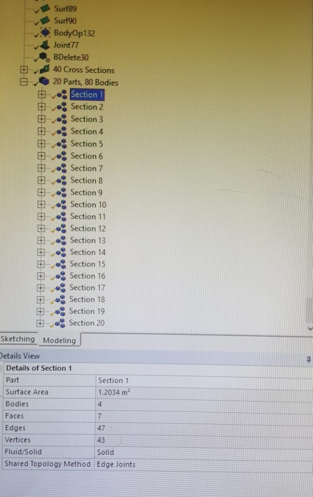
As shown in the attached figures, a single section consisted of skin (surface body), two spars (Line body- Two lines on top skin surface), and a rib (surface body). All were put in a single part. However, when I took that single part in Mechanical, a applied a load on one end (at rib) while fixing the other, the rib detached from the skin at some locations. However spars and skin were well connected.
Section 1 and Section 3 are shown here. (Section 2 used for joining them is hidden for clarity)
But then I went back on DM and created "Joints" (Tools>Joints) by selecting all 4 bodies in that part. It worked as can be seen by "Edge joints" view in Figure. Also worked fine in mechanical.
Now, my individual sections are joined. But I want to perform analysis on the complete wing. I want back on DM and created single part of whole wing. Applied joints on whole geometry but that did not work as some edge joints on ribs (meaning skins connection) were broken, rest was fine. Problem was with creating contact between two surface bodies (Skins) lying side to side. Had a lot of trouble with that. So reading another one of your post on "Contacts" where you mentioned it was better to select "Edges" of surface bodies as contact and target. I did that and it worked. Whole wing seems connected as I can see the stress flowing from one skin to another. (All contact automatically created by Mechanical were suppressed).
Although my problem is now solved, point of sharing this is for the benefit of other users.
My question is, did I adopt the right approach? and also
Is is possible to use the Model created in Mechanical (Static structural) to carry out modal analysis as joining individual sections using "Mutual contact region" again will require some effort in Modal.
-
May 2, 2020 at 11:09 am
peteroznewman
SubscriberDo not use Joints to fix together edges because all the force must go through a single point. Even worse is if the Joint behavior is set to Rigid, which creates artificial stiffness in the structure.
Bonded contact distributes the connection along the edge, which is acceptable.
Shared Topology from SpaceClaim or DM is the best when it works properly.
Node Merge can give the same effect as Shared Topology, but you must carefully inspect the mesh for cracks.
Yes, you can drop a Modal analysis on the Model cell of the Static Structural in Workbench and all the contacts are automatically included. Open Mechanical and drag and drop the Fixed Support from Static Structural down to Modal.
If your question is answered, please click the Is Solution (when logged in) to mark this discussion as Solved.
-
May 4, 2020 at 6:05 am
KhizerKhan
Subscriber
Edge Joints
Edge Joints are essentially coincident edge pairs that are tracked in the ANSYS DesignModeler application.
They are created automatically by several features, such as the Surfaces From Edges and Lines
From Edges (p. 424) features. Edge joints can also be created by the Joint feature, where you choose
a set of bodies to join together. Edges that are paired in an edge joint must belong to bodies that
reside in the same part in order to share topology. During transfer of the model out of the ANSYS
DesignModeler application, each edge joint will combine its coincident source edges into a single
edge. The edge joint method cannot be applied to Solid (p. 195) bodies.
Above is quoted from Designer Modeler Manual.
Shared topology just doesn't seems to work for me. I made my whole geometry into a single Part and applied Shared Topography (It only shows me option for edge joints) . Once generated, it has no effect on the geometry (which is also visible from the yellow tick mark). Number of edges of the geometry remain same. (Share topography is done after merging all multi body parts together- Image below is taken before that).
Â
Is this because the edges are not same for different surface bodies. They were created from the same edge but once surface is created, if you zoom a little you can find different edges for different surfaces. Is this normal?
Also I used the joints option from the DM, which seemed to have worked for me. Isnt there any difference between the Joints in Mechanical and Joints created in DM?
-
- The topic ‘Thicknesses of different faces of a surface Body’ is closed to new replies.
-
5899
-
1906
-
1420
-
1306
-
1021
© 2026 Copyright ANSYS, Inc. All rights reserved.


.jpg?width=690&upscale=false)