We have an exciting announcement about badges coming in May 2025. Until then, we will temporarily stop issuing new badges for course completions and certifications. However, all completions will be recorded and fulfilled after May 2025.
Fluids

Fluids

Topics related to Fluent, CFX, Turbogrid and more.

Thermal Desktop Albedo Heating Rate Explanation

    • Alex
      Subscriber

      Hello, 
      I am trying to understand some discrepancies between albedo heating rates of identical surfaces on a six-sided, 1U CubeSat for an academic thesis. Below are sample results for a nadir-pointing satellite represented by a six-sided, black body box with one face-centered node per surface. The simulated orbit in TD is a basic Venus orbit with beta angle = 45 deg and altitude = 400 km, with 100,000 rays per node calculated over 3,600 positions. A constant albedo factor is input. The raw TD albedo heating rates are output over one orbit below:

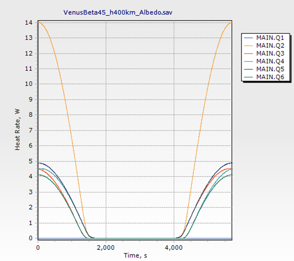
      (Q1 = Zenith, Q2 = Nadir, Q3 = Forward, Q4 = Aft, Q5 = North, Q6 = South)

      The naming convention I am using is:

      • Q1 = Zenith surface: faces away from the primary body, opposite the nadir one
      • Q2 = Nadir surface: faces the primary body and is tangent to its surface
      • Q3 = Forward surface: faces in the same direction as the satellite’s orbital velocity vector
      • Q4 = Aft surface: is opposite the forward surface
      • Q5 = North surface: faces in the out-of-page direction when viewing the orbit plane from the top-down
      • Q6 = South surface: is opposite the North surface

      May you please help explain:

      1) Why is the North albedo heating rate distinctly greater than the South albedo heating rate?

      2) Why is the Forward albedo heating rate greater than that of the Aft albedo heating rate before shadow entry for TD, but less than the Aft albedo heating rate after shadow exit?

      3) Why are the albedo heating rate curves spiky and not smooth? How can I smooth them?

      Rickman (https://tfaws.nasa.gov/wp-content/uploads/On-Orbit_Thermal_Environments_TFAWS_2014.pdf) estimates that the Forward, Aft, North, and South faces of the satellite experience the same albedo heating rate—each incident albedo rate is identically scaled with cos(solar zenith angle) = cos(orbit angle)*cos(beta angle). However, the albedo rates in TD are clearly unidentical for the Forward, Aft, North, and South surfaces.

      Thank you!

    • Doug Bell
      Ansys Employee

      1) Why is the North albedo heating rate distinctly greater than the South albedo heating rate?

      At 45 degrees beta, the subsolar point is South of the equator. Therefore, the North-facing side sees the insolated face of the planet and the South-facing side sees some of the dark side of the planet. There is no albedo (reflected solar) from the dark side of the planet.

      2) Why is the Forward albedo heating rate greater than that of the Aft albedo heating rate before shadow entry for TD, but less than the Aft albedo heating rate after shadow exit?

      Same reason as above. The forward side at shadow entry primarily sees the dark side of the planet and the back side primarily sees the insolated side of the planet.

      3) Why are the albedo heating rate curves spiky and not smooth? How can I smooth them?

      With ray tracing there will be statistical error. (see Heating Rate Error Calculations - if you need to register, use a school or business email domain) The closer your calculation point are around the orbit, the more noticable even a small error will be. To smooth the curve, you can do one of two things: shoot more rays until the error is not noticable or reduce the number of orbit points so the error is not noticable. As long as you have enough orbit points to linearly approximate your heating, you don't need more. More orbit points require more calculations and may also require more rays to reduce the noticable error: this amplifies the time to perform calculations with little gain in accuracy.

    • Doug Bell
      Ansys Employee

      I should note that when performing heating rate calculations, the best option is to set a high value for Max Rays per node (on the order of 1 million), set target error to a non-zero number (5% is usually reasonable unless you are using many orbit positions), and set Rays before error check to a statistically significant value (5000 is usually a good place to start). The code will shoot 5000 rays per node per source. The error will be estimated. If the target error has not been met, the number or rays needed will be estimated and shot and the error estimate updated.

      So instead of shooting 100,000 rays per node per source (solar, albedo, and planet IR), all nodes will shoot 5000 rays for each source. Node that don't see the source will not shoot more than 5000 rays for that source. For nodes that see a source with all rays at the same angle (such as for solar), only 5000 will be shot. For solar only 30000 rays will be shot for a 6-node cube. For albedo, the node on the zenith side will only shoot 5000 rays. The other 5 nodes will shoot more than that, but that one face saves 95000 rays.

Viewing 2 reply threads
  • You must be logged in to reply to this topic.