-
-
April 21, 2020 at 5:07 pm
PippoLomi
SubscriberHi everyone,
for master thesis I need to import a blade in TurboGrid for make the CFD analysis.
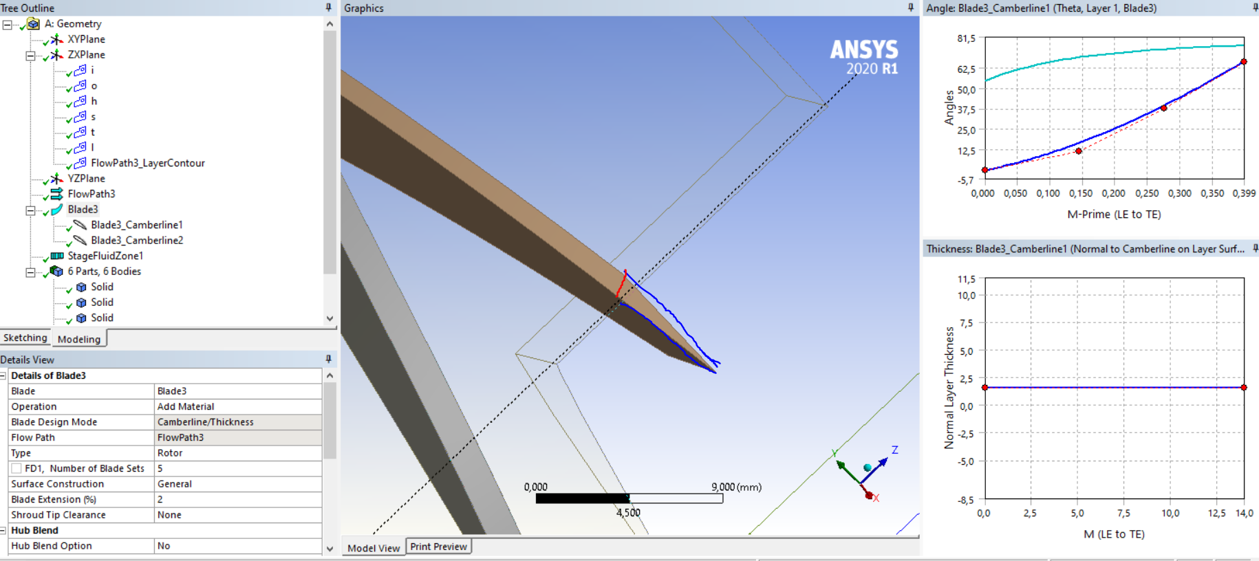
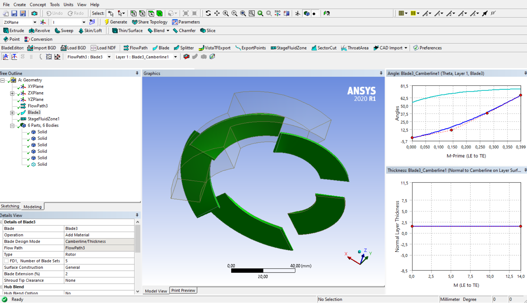
I started from two profile points, in 3D space. Then I imported in DM environment, and I made Skin/Loft operation between these two profiles. For now I'm analyzing a shrouded centrifugal compressor rotor, so I don't need clearance between tip and shroud.
When I defined the surface and FlowPath in DM, the blade surface was obtained usign Lofting command. The curves were closed, but only the blade surface was defined, without creating a surface of the hub/tip. So, watching the blade from the shroud, it seems to be "empty", in the sense that it has only the outer wall that defines the surface.
How can I define the hub/tip surface in DesignModeler environment (the surface that closes the blade surface)?
Thanks
-
April 22, 2020 at 5:12 am
Keyur Kanade
Ansys Employeecan you please insert some image and explain more clearly with some sketch and arrows.
you may want to see different surface creation methods in DM in help document.
-
April 22, 2020 at 6:35 am
PippoLomi
SubscriberGood morning Sir,
here attached are visible the photos of a generical view of the blade in CFX Pre and the photo oof the blade only.
As you can see, in the first photo, the blade seems to be "empty", because in DesignModeler I have used loft command between two closed 3D lines. Also, here below is show the DM window of the sketch.
The dimensions are referred to the inlet and outlet domain. The blade is constructed starting from the hub/tip contour.
Thank you
-
April 23, 2020 at 2:45 am
Keyur Kanade
Ansys EmployeePlease create surface at the blade.
use create surfaces from edges.
try to create blade as solid body in DM.
after creating surface, you may need to use 'sew' to form a solid.
please go through help for more details about these commands.
there are some videos as well on youtube.
Regards,
Keyur
If this helps, please mark this post as 'Is Solution' to help others.
Guidelines on the Student Community
How to access ANSYS help links
-
April 23, 2020 at 7:50 am
PippoLomi
SubscriberHi sir,
I have used the command "Surface from edges" for create the hub and tip surface, and works well. Here below there is the image that represents the surface at

the tip. Then I have created the hub surface, using the same command. I have used 0 m thickness both at the hub and at the tip. All the normals are flipped in a manner that I have the normal that is oriented outward (respect to the body).
However, when I used "Body Operation - Sew" it fails. Also, it cannot select the blade surface, made with command "skin/loft".
In the end, I try to make a new DM file. I imported the two 3D curves of hub and tip, I made loft operation for create the blade surface, I performed your suggested command for hub and tip but "sew" does not work.
What can be the problem?
Regards,
Filippo
-
April 24, 2020 at 5:11 am
Keyur Kanade
Ansys Employeeyou may want to split the curves and create 2 or 3 surfaces instead only one surface for blade.
Regards,
Keyur
If this helps, please mark this post as 'Is Solution' to help others.
Guidelines on the Student Community
How to access ANSYS help links
-
April 24, 2020 at 7:25 am
PippoLomi
SubscriberHi sir,
I have already splitted the hub and tip curves, for create revolution surfaces of hub and shroud. So your suggestion is to use that pieces for create two or more lofting on blade surface or on tip and hub surfaces?
Also I thought that the fluid interacts only with the blade surfaces, made with lofting operation, between the two curves described in earlier messages. If I don't have a clearance between tip and shroud (and other feature, always present in a real machine), is it correct model the domain in this way, with the "empty" blade like in figures above?
Also, when I want to model a compressor with clearance between the blades, is it possible add the shroud tip clearance ONLY in turbogrid? The graphical result seems to give good results.
Regards,
Filippo
-
April 29, 2020 at 6:33 am
PippoLomi
SubscriberHi mr kkanade,
I hope that you have already read my questions.
Do you have any suggestion?
Thanks
-
June 8, 2023 at 12:00 pm
Mustafa Babagiray
SubscriberHi everyone,
I am trying to make a CFD simulation for the axial turbine. I created the blades in the blade modeler in DM. The turbine blades that we use in real have a constant thickness from the leading edge to the trailing edge and I wanted to do the same thing in design modeler but it gives me airfoil instead. As you can see in the picture, the tip of the blade has a sharp edge, I want it to be a flat surface. I mean when you look at the shroud the top surface of the blade should be rectangular. Do you have any suggestions about it?
As you see the blue line represents the current tip of the blade and I am trying to make it as red line. The full illustration of the blades can be shown below.
Thanks in advance
-
- The topic ‘Blade and DesignModeler’ is closed to new replies.
-
6455
-
1906
-
1457
-
1308
-
1022
© 2026 Copyright ANSYS, Inc. All rights reserved.


