Photonics

Photonics

Topics related to Lumerical and more.

Quality factor from Interconnect ONA

    • adevata
      Subscriber

      Hello,

      I am confused on how INTC's ONA element calculates Q-factors. I have created an add-drop ring resonator (heavily inspired by this example) that I want to extract the Q-factor of. I understand that Q = f0/f_FWHM, and that the spectral response follows a Lorentzian. I've extracted the spectral data from the ONA and externally fit the Lorentzian parameters to calculate Q, resulting in an excellent fit. However, this Q-factor does not match the Q-factor that INTC spits out. Additionally, the Q-factor from INTC changes depending on the FWHM excursion that is set, however the spectral data does not change.  

      Is there a formula, algorithm, or fitting routine used by the ONA to obtain the Q-factor for a set of collected spectral data? If so, is this publicly available, and if not, how can I replicate the Q-factor that is returned? 

      In case this matters, I am using both an excess loss and the frequency-dependent propagation loss from my FDE simulations. I can confirm that changing the excess loss changes the spectral response, and thus the Q-factor.

      Any and all insight would be greatly appreciated. Thank you for your time and help, and I look forward to your reply!

      -AD

    • Afroditi Petropoulou
      Ansys Employee

      Hello and thank you for contacting us,


      The quality factor can have different definitions as explained in Quality factor calculations for a resonant cavity – Ansys Optics.

      I also checked the Ring Modulator – Ansys Optics example and even with the Q= f/df definition I get reasonable results (1.5-2 times higher) but this is not surprising considering the different definitions.


      Best regards,

      Afroditi

    • adevata
      Subscriber

      Hi Afroditi,

      Thanks for your reply. I am still a little confused: In INTC, I am providing files that represent the extrinsic and intrinsic coupling losses (FDTD simulation of coupling region, FDE simulation of straight and bent waveguides, etc). The output is a spectral response (transmission vs wavelength). Moreover, the link you provided seems to be specific for FDTD. This is the only link on Lumerical's documentation for INTC that mentioned Q factor, but it does not answer my questions.

      I have an external fitting routine that will extract all relevant figures of merit from INTC's spectral response (Q factor, FWHM, extinction ratio, center frequency, etc). I fit the transmission data to a Lorentzian to obtain the FWHM and center frequency, then using Q = f/df, I am able to calculate the Q factor. I have made sure to convert from wavelength to frequency and use the transmission from 0-1 instead of dB for this routine.

      1. Assuming the output spectral response from INTC is correct, why does INTC's corresponding Q factor not match? For some simulations, the order of magnitude is correct, but for larger Qs, it tends to be larger by a factor of 10-100. The link you provided acknowledges there are multiple ways to calculate the Q factor, however it seems to be specific for FDTD simulations since it refers to simulation time and field decay. What are the Q factor calculations used by INTC's ONA?
      2. Additionally, why does this Q factor change (by up to 30%) depending on what I set the FWHM excursion to? The spectral response is identical in both cases, which further confuses me on how INTC's ONA is actually calculating the Q factor.
      3. I didn't mention this in the original post, but INTC's spectral response seems to be giving quality factors 20-25% higher than when I manually calculate the Q factor using the intrinsic and extrinsic loss rates. This makes me suspicious of the actual spectral response. Do you have any insight into this problem as well? I am using extrinsic coupling loss from FDTD, intrinsic coupling loss from FDE (bending and mode/power confinement, I was told that these were all automatically accounted for), as well as an excess loss in INTC. 

      I would greatly appreciate any and all help you can provide to resolve this issue. Thank you for your time and help, and I look forward to your reply!
      - AD

    • Afroditi Petropoulou
      Ansys Employee

      Hello,


      I discussed this with our R&D and the Q factor is indeed calculated as fr/FWHM.

      ONA also reports the resonance frequency, which can be found under peak/frequency and the FWHM, which can be found under peak/bandwidth. If you divide these values, you will get the Q factors calculated from the ONA.


      Best regards,

      Afroditi

    • adevata
      Subscriber

      Hi Afroditi,

      Thank you again for your reply and checking with the R&D team! I did some testing on one of my peaks and attached a picture of the results below. From what I can tell, it is correct that Q is calculated using f0/df. However, it seems that the value used for df is determined by the bandwidth set by the FWHM excursion setting, and not the actual full width at half maximum of the spectral response. Since the standard definition for Q (e.g., per wikipedia) is for df to use the true FWHM, I would expect Q to remain constant for a fixed resonance peak. Instead, ONA's reported Q varies significantly with the FWHM excursion setting, even though the spectral data itself is unchanged.
      Do you have any recommendations for configuring the ONA so that it reports the Q factor based on the actual FWHM, rather than one tied to the excursion setting? As it stands, the current behavior makes it difficult to use the built-in Q reliably.

      More importantly, I am still unsure how to reconcile the Q factor I compute directly from my input component data (I used the math from this textbook) with the one extracted from INTC's spectral response. Specifically using the intrinsic and extrinsic loss rates I input (from FDTD and FDE simulations, plus manually specified excess losses), I calculate a Q that is consistently 20-25% lower than what I get from Lorentzian fits to the simulated INTC spectra. These fits are very accurate in both the pass and drop ports, and my fitted Q factors for both ports are nearly identical to each other. This makes me question whether all the losses are being correctly accounted for in the simulation.
      Could you clarify which loss mechanisms are included in INTC's spectral generation, and whether there are known issues or assumptions that may cause this discrepancy? Additionally, how exactly is INTC generating the spectra that is returned in the drop and pass ports?

      I appreciate your time and help in resolving these!
      - AD

      • adevata
        Subscriber

        Apologies, I forgot to attach my pictures!

        Thank you!
        -AD

    • Afroditi Petropoulou
      Ansys Employee

      Hello AD,


      I checked again and I can confirm that the FWHM is calculated from INTERCONNECT without any fitting, just by simply searching for upper and lower values and taken at -3dB from peak value. When you get the transmission values to perform the Lorentzian fit, do you use the Abs^2 of the transmission? The transmission result from ONA is the complex transmission as explained in the results section of Optical Network Analyzer (ONA) - INTERCONNECT Element – Ansys Optics, hence, you need to take the Abs^2 of it to calculate the power.


      Regarding the losses, the losses calculated from FDE solver are considered in the MODE Waveguide (WGD) - INTERCONNECT Element – Ansys Optics if the “propagation loss” option is set to “false”. If 'true' is selected, the propagation loss will be ignored.

      Also, there are two other options of loss that can be added on top of the propagation loss, the “loss” in dB/m and the “excess loss” in dB:


      Best regards,

      Afroditi

    • adevata
      Subscriber

      Hi Afroditi,

      Thanks again for your reply! I am using the gain function on the ONA, so the values the ONA returns are in dB. This is identical to Lumerical's ring modulator example I linked earlier. I am converting these values from dB into power (normalized to a range of 0-1) and am getting excellent fits with my fitting routine. My understanding is that gain (or even converted gain) should never require the Abs^2 function, but please correct me if I am wrong. Apologies for the miscommunication, I had mentioned transmission in my previous messages but I meant the gain function.

      How can I get this value of FWHM that you mention from the ONA? As I showed in my pictures, the bandwidth does not return the FWHM. Setting the FWHM excursion to -3dB and extracting the bandwidth will not consistently work for my script as my peaks can drastically vary in height (extinction ratio). If I want the FWHM of my self-normalized peaks, the currently implemented FWHM excursion will not work for my case. Please let me know if you would like more data for this, I can create a more thorough analysis of the data similar to the images I attached.

      Apologies for the confusion on the losses. I am more interested in how INTC implements these various losses from coupling coefficients, mode simulations, and loss/excess loss parameters in calculating the final spectral response.You had already mentioned in a previous thread that the excess loss can be used to add additional loss components to the system, which I have already implemented. However, the response I am getting is not consistent with my theory calculations.

      For additional clarity, there are 3 methods on which Q-factor comparisions can be made: 1) the gain data from INTC's ONA, 2) my fitting routine that fits the converted gain data to a Lorentzian, and 3) the theoretical Q factor based on FDTD, FDE, and excess loss parameters that are obtained directly from the component simulations. 1 and 2 match nearly identically, but they are off by 20-25% from 3. Since 3 is lower, it leads me to believe that INTC is not incorporating all of the loss parameters I am providing it. However, I have no way of debugging this discrepancy unless I learn more about the backend of how INTC is calculating these spectral responses. This is now the primary issue I am focused on, so any help, insight, or feedback would be greatly appreciated.

      Thank you again for your help!

      -AD

    • Afroditi Petropoulou
      Ansys Employee

      Hello AD,


      If you plot the transmission result from the ONA, you will see the resonances of the cavity. Here is an example of the abs(T)^2 from the ring resonator:

      A graph with blue lines

AI-generated content may be incorrect. 

      If you take the first resonance at 1505.23nm and check the FWHM is ~0.07nm. You can check it if you zoom in around abs(T)^2=0.5:

      A graph with lines in it

AI-generated content may be incorrect.

      This is also the value calculated from INTERCONNECT if you check the bandwidth result (which is also used for the Q factor calculation):

      A graph with red and blue dots

AI-generated content may be incorrect.

      Even when I check the gain result, I get the same value for -3dB which corresponds to half maximum (10log(PFWHM/Pmax)=10log(0.5)=-3dB):

      A graph with blue lines

AI-generated content may be incorrect.


      If you have the values in dB, why do you need to convert them back to power?


      I am not sure why your fitting gives you different results, but when I check the ring modulator example, I get the values reported by the ONA. If you check the results without any fitting, do you get the FWHM calculated by the ONA?


      Regarding the losses, how do you compare the results between INTERCONNECT and FDE or FDTD? What is the difference that you get? To compare the results, you should not add any excess loss just the one calculated from FDE.


      Best regards,

      Afroditi

      • adevata
        Subscriber

        Hi Afroditi,

        I am converting from gain [dB] to normalized power (range from 0-1) to perform the Lorentzian fit, it is unphysical to fit values in dB to a Lorentzian.

        I think the example you shared is of a more ideal case. I am trying to accurately capture the additional losses in my system, so some of my peaks will never reach 0 for abs(T)^2.
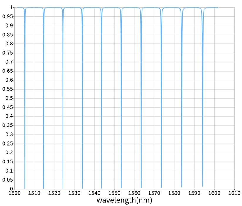
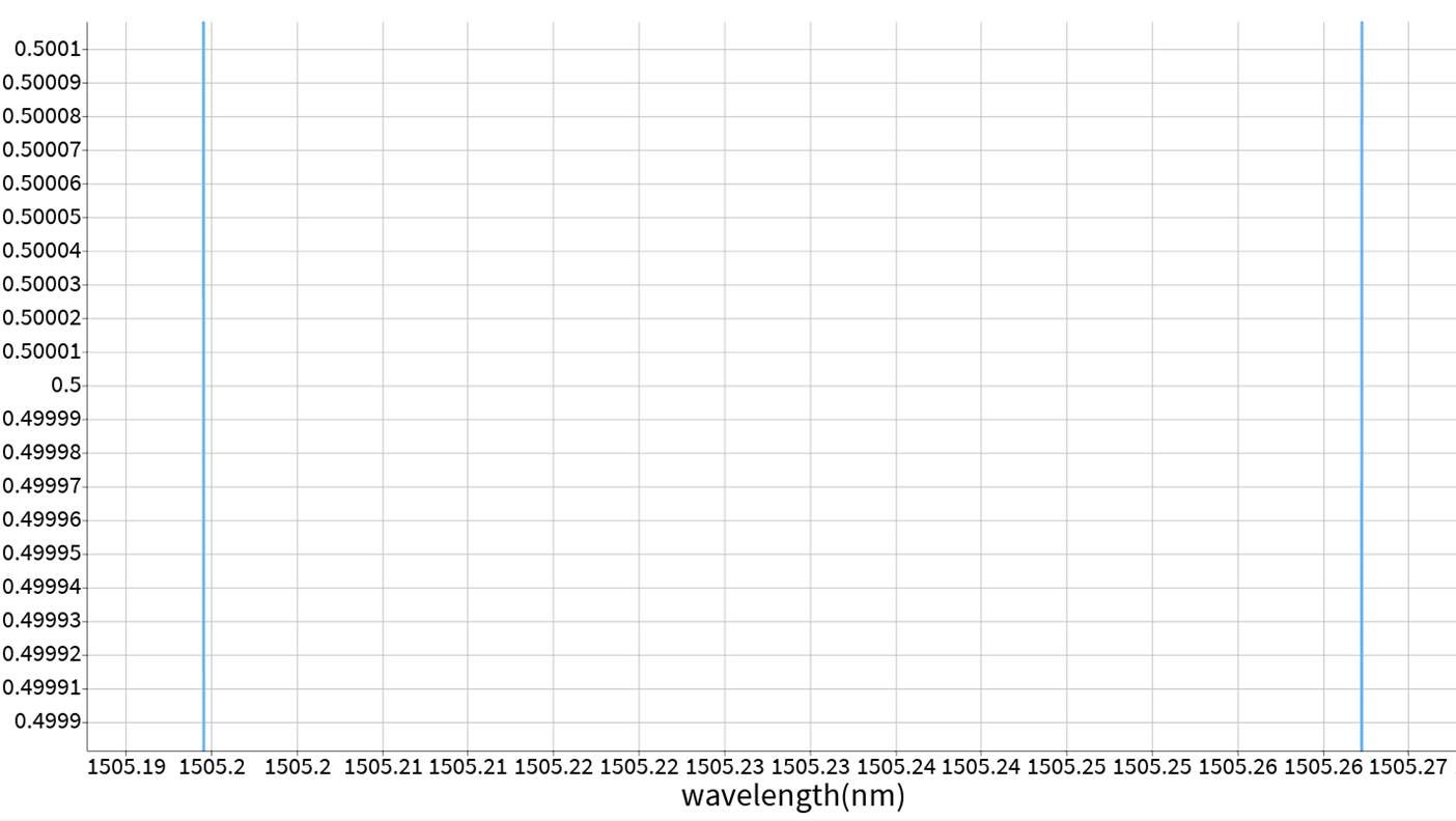
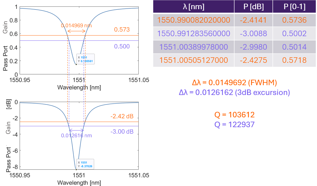
        For example, one of my peaks has an extinction ratio (ER) of 8.37 dB, which corresponds to a minima of 0.145. This means that the range of the peak is from 0.145 to 1, so its height is 0.855. Therefore the half maximum point would be at 0.145 + 1/2 * 0.855 = 0.573, which corresponds to 2.42 dB. The width in question for the FWHM is at this value of 2.42 dB, not the 3 dB (0.5) mark. As a result, to get the bandwidth to return the desired width (the FWHM), I need to set FWHM excursion it to 2.42 dB, NOT 3 dB. I've attached a picture below, purple corresponds to the FWHM excursion with 3dB, and is equivalent to what you sent in your message; orange corresponds to the FWHM for a lossy peak.
        Unfortunately, since my peaks all have different extinction ratios, I cannot set them all to the same FWHM excursion in order to get the FWHM I need. Based on this, do you have any advice to obtain the FWHM for my peaks? For further context, this is in a script that varies 7-8 different parameters.

        As for the losses, I am using theory from Ch. 3 of Heebner's Optical Microresonators: Theory, Fabrication, and Applications. The formula for Q is as follows:
        Q = (2*pi*n_eff)  /  (alpha_dis*lambda), where alpha_dis is the distributed loss [1/m, not dB/m] in the ring, including coupling, bending, and propagation losses. The formula for alpha_dis is as follows:
        alpha_dis = alpha_ring + alpha_coupling
        alpha_ring = alpha_bend + alpha_prop     (intrinsic losses)
        alpha_coupling = -2*ln(1-kappa)/(2*pi*R)     (extrinsic losses)

        • n_eff comes directly from FDE, which is input using .ldf file according to the ring modulator example.
        • alpha_bend (bending loss) comes directly from FDE, which is input using .ldf file.
        • alpha_prop (propagation loss) is inputted as excess loss into INTC as a number [dB/m].
        • kappa is the power coupling coefficient which is calculated from the S-matrix from FDTD, and imported using a .txt file.

        For example, using the same peak as above:

        1. I have set radius to 60 um, and center wavelength (lambda) to 1550 nm. lambda may be off by at most 1-2 nm, which is at most 0.13% off (even when calculated from the reciprocal as lambda appears in the denominator of Q), and does not fully explain the 20-25% difference between calculations.
        2. FDTD tells me that kappa(lambda=1550nm) = 0.0105025 --> alpha_coupling = 56.0123 1/m
        3. FDE tells me that n_eff(lambda=1550nm) = 1.9750352.
        4. FDE also tells me that the bending loss is 1.87245 dB/m, which is equivalent to 0.4311481 1/m.
        5. My excess loss into INTC is 1.5 dB/cm, which is equivalent to equivalent to 34.5388 1/m. This represents propagation loss from scattering or sidewall roughness.
        6. Based on 4 and 5, alpha_ring = 34.5388 1/m + 0.4311481 1/m = 34.9699 1/m
        7. Combining 2 and 6 gives alpha_dis = 90.9822 1/m
        8. Plugging 1, 3, and 7 into the formula for Q gives Q=87997.

        Comparing 8 to the orange value in the picture above, gives a 18% error. Based on this, I am curious to how INTC is actually calculating the spectral response of my system. Could you please provide some insight into this discrepancy?
        Additionally, can you explain why I should not be considering excess loss? That term is critical for me to model my realistic system, and due to how ring resonators operate by balancing different loss components, it is absolutely critical that all loss terms are accounted for, especially as we start reaching higher Q factors.

        Thank you for your help and insight!
        - AD

    • Afroditi Petropoulou
      Ansys Employee

      Hello AD,


      Thank you for the clarification. I see your point.

      It is true that the FWHM will be calculated using the “fwhm excursion”.

      I also did a simple test of a micro-ring resonator with low coupling constant to get a spectrum similar to what you are discussing:


      A graph of a graph

AI-generated content may be incorrect.

      In this case even the lowest transmission value is higher than -3dB, hence, the calculated FWHM is 0. When I set the “fwhm excursion” to 0.75dB which corresponds approximately to the middle of the resonance I get the correct FWHM.

      In this case you can either set the “fwhm excursion” to a value that corresponds to your peaks or, in case you don’t know it from the start (which is the most reasonable) you can calculate the Q factor with a post-processing script and Lorentzian fits as you already do.


      Regarding the losses, INTERCONNECT should calculate the losses correctly according to the inputs and the lengths of the waveguides. I am not familiar with the Q factor calculation you mentioned, and I don’t know if I makes any assumptions or not. I guess when using the equation, it is assumed that the losses are only in the ring, and you don’t add them to the straight waveguides. Does the equation consider both bus and drop waveguides?


      By not adding excess loss, I meant if you wanted to directly compare INTERCONNECT results with and without loss from FDE or FDTD (for example straight waveguide with and without loss to see that the loss is calculated according to the dB/cm value). Since you compare this to a theoretical result, of course you can use the excess loss. Even in the direct comparison I would first check that the loss calculated from FDE is correct and then I would add excess loss to check it too. A step-by-step analysis is easier for debugging.


      Best regards,

      Afroditi

Viewing 8 reply threads
  • You must be logged in to reply to this topic.