General Mechanical

General Mechanical

Topics related to Mechanical Enterprise, Motion, Additive Print and more.

MbD and FEM of a simple pendulum.

    • josegegas
      Subscriber

      Dear. 

      I have been strugling for some time to simulate the dynamics and FEM of a simple pendulum. The final objective would be to obtain the stress of the pendulum and the pin it swings on. Here is a detailed explanation of what I need to achieve:

      https://mbdfem.com/

      How can I do this in Ansys?

      Thanks in advance,

    • peteroznewman
      Subscriber

      Others may want to refer to a previous discussion that answered this question with a couple of example models and videos.

      https://innovationspace.ansys.com/forum/forums/topic/how-joint-force-is-distributed-among-fem-nodes-in-transient-simulation/

    • josegegas
      Subscriber

      The previous discussion offered only a partial solution (inertia relief and contact), but it did not answer to several questions:

      1 How to instruct Ansys to distribute joint force loads over the fem nodes?

      2 How to instruct Ansys to distribute joint torque loads over the fem nodes?

      3 Once joint loads are distributed to the FEM nodes, how to know how Ansys actually distributes the loads? Over which nodes? What is the load vector for each node?

      4 How to solve for all time-steps? 

      5 How does "inertia relief" actually works? A brief description of the math formulation would be helpful, to understand what Ansys is actually doing.

      Thanks.

    • peteroznewman
      Subscriber

      In Ansys, two models compute different types of useful results. The two models are 1) Rigid Dynamics which uses a revolute joint and 2) Transient Structural which uses frictional contact and no joints.

      The Rigid Dynamics model outputs the peak total force going through the revolute joint. A Static Structural analysis is used with Inertia Relief to apply that peak total force to the hole and distribute it to the nodes using a Bearing Load. That was shown in this video: https://www.youtube.com/embed/2y313lIoXko

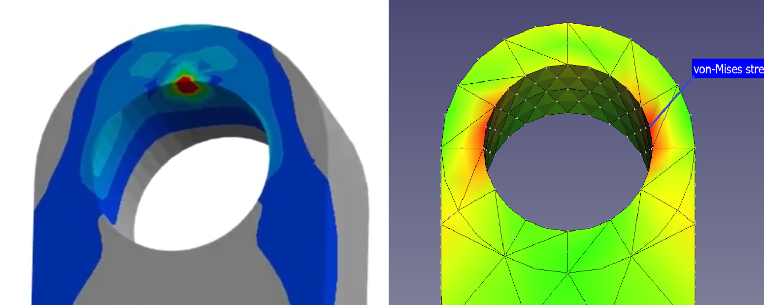
      The Transient Structural model with frictional contact allows complex contact conditions to be resolved, such as a shoulder pin in a clearance hole with the pin axis tilted away from horizontal to create a moment (torque) that causes the clearance to be taken up on opposite sides of the hole as shown in this video: https://www.youtube.com/embed/7elKN8FJoKI

       The Rigid Dynamics model is quick and easy to build and solve, but is limited in scope.  The Transient Structural model takes more time to build and solve, but has the ability to accurately distribute nodal forces to model clearance between the pin and hole and have the face of the pendulum supported on the shoulder. The analysis is modeling a realistic condition with little idealization.

      Section 1.12 of mdbfem.com includes a tilted pin but does not accurately represent nodal contact forces created by realistic geometry that includes clearance and a shoulder to support the axial forces. It is modeling an idealization because it is using a hinge joint.

      Here are my answers to your questions.

      1 How to instruct Ansys to distribute joint force loads over the fem nodes?

      Answered above with two models.

      2 How to instruct Ansys to distribute joint torque loads over the fem nodes?

      Use the Transient Structural full contact model as described above.

      3 Once joint loads are distributed to the FEM nodes, how to know how Ansys actually distributes the loads? Over which nodes? What is the load vector for each node?

      In Transient Structural, nodes that have a closed contact status generate a normal force to prevent penetration and a tangential force to apply friction to resist sliding. The forces are calculated to put the model in dynamic equilibrium at each time step.

      4 How to solve for all time-steps?

      The Transient Structural solution solves for all time steps.

      5 How does "inertia relief" actually works? A brief description of the math formulation would be helpful, to understand what Ansys is actually doing.

      The theory manual describes how inertia relief works. https://ansyshelp.ansys.com/public/account/secured?returnurl=/Views/Secured/corp/v251/en/ans_thry/thy_tool2.html

    • josegegas
      Subscriber
      Hi. We have now a more realistic distribution of the FEM loads derived from joint force and torque. We added shoulders to the pin
      in order to avoid adding un-realistic axial loads to the cylindrical face.
      We also use different profiles (linear, sine and triangle), for the force and torque FEM loads.
      However, we still have not been able to obtain consistent stress results from both Ansys and our combination of MBDyn and Calculix. To recap:
      Ansys and MBDyn output almost exactly the same joint forces and torques. But when these forces and torques are applied to a static
      structural simulation using Ansys inertia relief, the resulting stresses make no sense. We still do not know how to obtain a realistic
      stress distribution from the static analysis with inertia relief and the force and torque from rigid dynamics.
      Also, the Ansys transient simulation produces a very different stress too, inconsistent with our simulation.
      I suspect that the reason is that, unlike what is shown in the video you shared above, in our simulation we assume that there is no
      clearance between the pin and the pendulum. Can this explain the discrepancy? This is the difference between Ansys and MBdyn/Calculix:
       
       
      You can have a look a a detailed explanantion of the MBDyn/Calculix simulation here:
       

      https://mbdfem.com/obliquePinPendulum.html

       
      I would love to understand what is going on. Thak you very much.
Viewing 4 reply threads
  • You must be logged in to reply to this topic.