-
-
April 8, 2020 at 12:35 pm
Martin2019
SubscriberHow can i rotate a permanent magnet for a magnetostatic sweep analysis in Maxwell?
I want to calculate the Torque over a range of the angle in a sweep analysis.
My magnet rotates but the Field does not. Its a problem with the Coordinate System, how can i rotate the CS with the magnet together?
-
April 9, 2020 at 1:00 pm
Sadegh
SubscriberHi Martin
in order to rotate an object by steps, you can simply select the object --> choose the rotate operation from the top taskbar--> a small window pop-ups and ask you how much angle (in degree by default) you want to rotate the object. instead of inserting numbers, write a variable (for example. "rotation") then click OK--> another small window pop-ups and ask you to define the variable. you could give it a 0 for now.
then from Optemtric in project manager you should click on add then parametric.
in the new window, click on add then select your variable, choose the method of variation then click OK
be careful to check "save Field and Mesh" from option tab .
-
April 10, 2020 at 1:01 pm
Martin2019
SubscriberMany thanks for your response. I know these steps. What I didn't activate was "Save Fields and Mesh" but that didn't change my problem. I have a round magnet. However, the magnetic field does not appear to be rotating, since all torques are almost the same.
How can I rotate a coordinate system with the body so that the magnetic field also rotates?
" alt="" width="235" height="391"> -
April 13, 2020 at 2:39 pm
Paul Larsen
Ansys EmployeeHi Martin, For permanent magnet you have two options:
1) You could change the material definition and define it as a function of the same angle. As I think of this, it is the harder method here because you would likely need a project variable, so let's skip to method 2...
2) You should create a relative coordinate system. You could use a general rotated relative coordinate system that is defined as a function of the angle. But I recommend using either an object-based or face-based relative coordinate system. Then you can just click on two points of the object, and the coordinate system should follow any changes that have been defined to the object already, such as a rotation. The final point to remember when using a relative coordinate system for material properties is to assign the object's orientation property to the relative coordinate system.
Note that this is required only for static simulations or when the position is defined without transient motion. In a transient motion model (such as an electric machine), the magnetization direction is evaluated based on the defined geometry ("Time=-1s"), and then the relative (rotated) orientations for all the "moving" objects is kept constant over time as initially defined.
-
April 14, 2020 at 6:23 pm
Martin2019
SubscriberHello pblarsen,
Thank you very much I found the problem. The CS must be at the end (after the rotation command) in the history tree. There is the command "Move to End" That was the problem.
-
October 27, 2023 at 6:49 am
Swarup Tripathy
SubscriberAdding to the main question, [using Ansys Electronics Desktop Student]
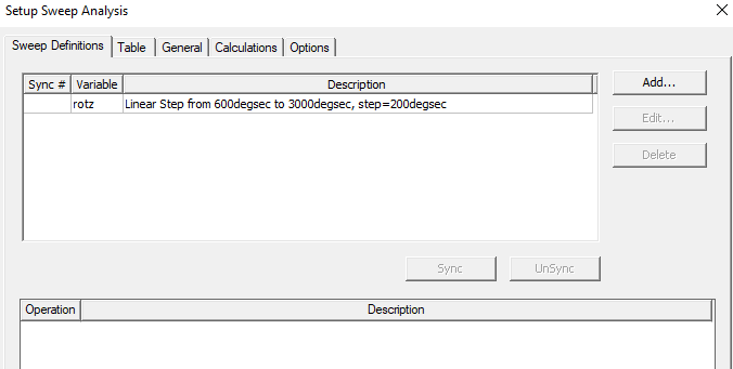
Q: I wish to rotate a disc comprising permanent magnets from 100 rpm (600deg/s) to 500 rpm (3000deg/s). Below, I have attached the 'setup sweep analysis' where the variable has been assigned to the magnet disc with the pm.
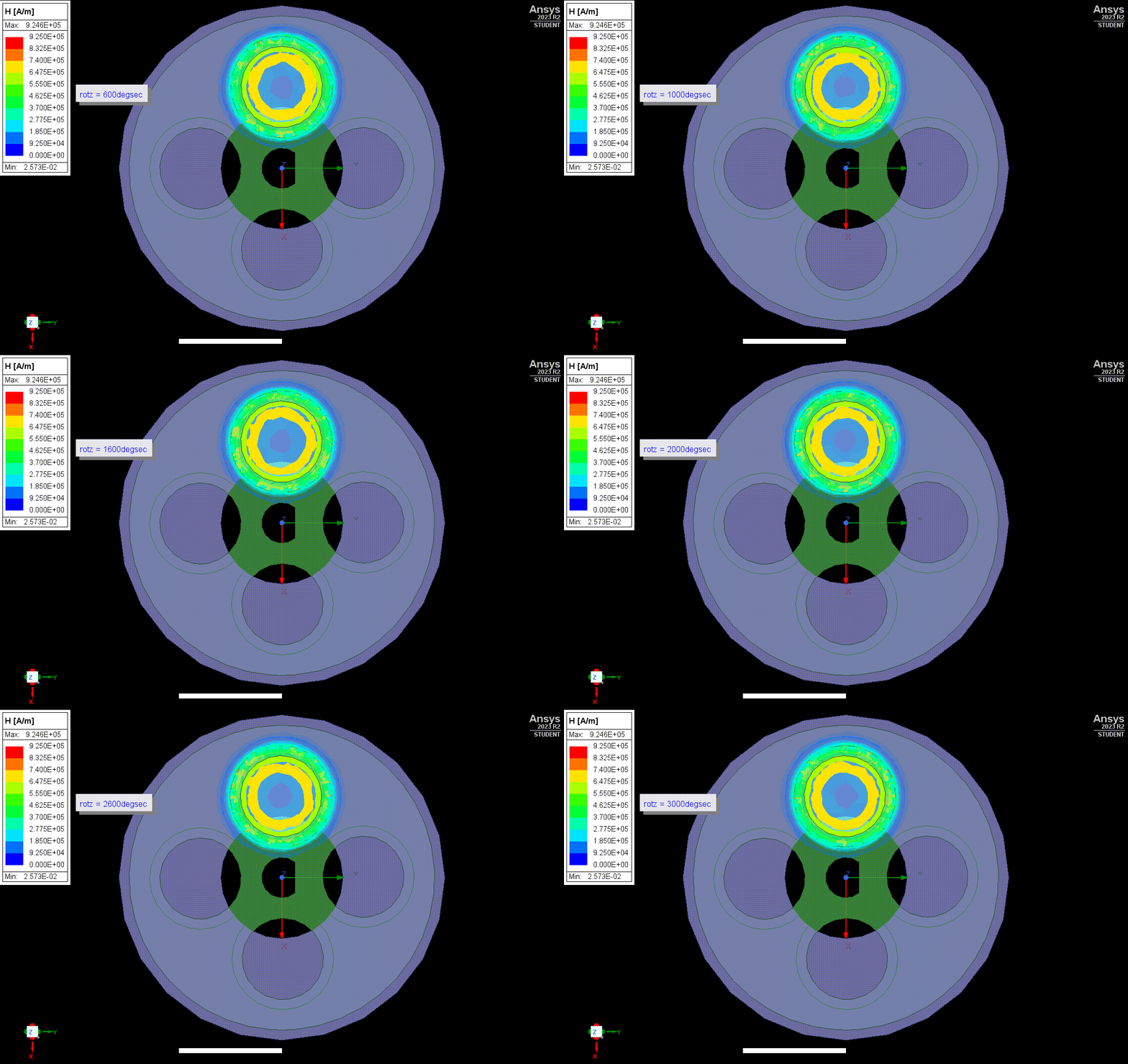
The resulting movement is shown below (animation speed has been increased to show the rotation)
Q1: Since I am fairly new to using Ansys Maxwell, I wanted to know if I am proceeding in the right direction or not, and is it possible to rotate the disc at a constant rpm?
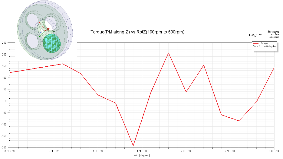
Q2: Below is a graph that displays the torque by 1 PM along the Z axis vs. the rotation. Here, I couldn't understand why the torque decreases and shoots when we increase the rpm of the magnetic disc comprising PM.

Your explanations would be really helpful!
-
- The topic ‘Rotating a permanent magnet and calculation of the torque’ is closed to new replies.


-
4678
-
1565
-
1386
-
1242
-
1021

© 2025 Copyright ANSYS, Inc. All rights reserved.


