TAGGED: Static-structure
-
-
April 2, 2020 at 9:06 pm
-
April 2, 2020 at 11:25 pm
peteroznewman
SubscriberIncreasing stress with decreasing element size is typical.Â
You should reduce the element size in a region around the maximum stress. If you put a Coordinate System at that location, then you can do Mesh Sizing control on a solid using the Sphere of Influence and select the Coordinate System so the elements only get smaller in a local region.
-
April 3, 2020 at 9:43 am
Amin1372
SubscriberThanks Peter. So if you look at the image below, one tooth has the maximum stress. Do I need to just reduce the element size of this tooth and keep the element size of the other teeth unchanged? also, I used body sizing and contact sizing (between teeth and vibratory device) for each teeth. which one should I play with ?
Â
Â
Â
Â
Â
-
April 3, 2020 at 5:09 pm
peteroznewman
SubscriberIf you double click on the blue square at the bottom of the legend, you can replace the dark blue with light grey and the image will be much easier to see the elements.
You can reduce the size locally on that tooth and maybe on the contact sizing.
-
April 3, 2020 at 5:30 pm
Amin1372
SubscriberSorry for the unclear image. So if I reduce the contact size of that tooth until the changes in stress get stable, this is would be the optimum element size and converge point, right? and I don't need to use that element size for the rest of the teeth? because my computer cannot run this for finer mesh size due to insufficient memory.
Â
-
April 3, 2020 at 6:36 pm
peteroznewman
SubscriberYes, just a local mesh refinement near the point of maximum stress.
-
April 6, 2020 at 9:26 am
Amin1372
SubscriberHi Peter,
I conducted mesh refinement near the point of maximum stress but my model didn't converge. In each refinement, the point of maximum stress is changed from one tooth to another one however I just reduced the element size of the initial point. Is that true? and what should I do for convergence test? And could you please look at my model?
Â
-
April 6, 2020 at 12:43 pm
peteroznewman
SubscriberYou can't do convergence if the maximum point jumps from one location to another. You have to plot the same location. Also, I can't see the values on your plot.
-
April 6, 2020 at 12:49 pm
-
April 6, 2020 at 8:17 pm
peteroznewman
SubscriberYou have a Modal Superposition Harmonic Response analysis.
Why do you have a force in the Z direction on the red face?
How is this device supposed to work?
The traditional Static Structural mesh convergence study may not work well here because there is a large amount of idealization and simplification going on between the elements and the solution. The whole model is being boiled down to 6 equations of motion because you only have six modes. The Frictional contact is being replaced with No Separation contact which can create artifacts in the stress distribution. I think what you were plotting above was noise.Â
Look at the Participation Factor Summary for the six modes you had. See how the X-direction is very low and the Y-direction jumps up suddenly. But worst of all is that the Ratio of Effective Mass was not computed.
I changed it to 30 modes and the results show a more gradual build-up of mass, but most important, the Ratio is now calculated. The problem is that the Sum of the Effective Mass to Total Mass is only up to 42-56% but to have a good result, the Sum should be over 80%.
Try 100 modes and see if the Sum of the Ratios of Effective Mass to Total Mass is > 0.8
Finally, I noticed in the Solution Statistics that you have a 4 core computer, but you only used 2 cores to solve the model. You will have a shorter wait time if you set the number of cores to 4.
-
April 6, 2020 at 8:54 pm
Amin1372
SubscriberHi Peter and thanks for your help.Â
The force in Z direction on the red face is the magnitude of the force applied by the device which is a vibratory device with frequency of 30 Hz. Shouldn't I define that like what I did?
I will use 100 modes to see the Ratios of Effective Mass but if I use Transient Structural Analysis, will that be faster? -
April 6, 2020 at 9:11 pm
peteroznewman
SubscriberI just ran 100 modes, the Z axis is up to 74%.
Do you mean that inside the blob sticking out the front is a mini shaker that operates in the Z direction? It isn't on the thin beam between the blob and the bite plate is it?
Transient Structural will be much, much slower (days or weeks).
It might be better to run the solutions in cm,g rather than mm, kg, because the mass ends up being measured in tonnes and the values are tiny.
-
April 6, 2020 at 9:38 pm
Amin1372
Subscriber -
April 6, 2020 at 9:51 pm
peteroznewman
SubscriberIf the vibratory source is inside the blob, then that is where the force should be applied. The beam is just bending.
Here is the result for 200 modes. Now it is getting close.
That used 58 GB of RAM and took 25 minutes on 15 cores using the Direct solver.
You can reduce the memory requirements by using the Iterative solver.
I don't know if you can get mesh convergence in this model.
What is the true mass of the device? You have one silicone body with a 30 g mass. I expect that is incorrect. The true device has a battery and a shaker and that will have a much heavier mass. The true device also has a plastic bite plate covered in silicone rubber.
-
April 6, 2020 at 10:03 pm
Amin1372
SubscriberI think you are right. I need to put the force on the vibratory source instead of beam.Â
But I don't know what I can do for mesh convergence as I have a common laptop !!!!!!
Â
Thanks a lot Peter
-
April 6, 2020 at 10:28 pm
peteroznewman
SubscriberSo when I run the Harmonic Response with 200 modes, the stress for the 0.2 mm mesh size is 0.381 MPa which is a significant change from the 0.325 for 6 modes using the same mesh.
However, moving the force application point back onto the slanted face of the blob, the stress raises to 0.68 MPa.
One of the many issues I have with this model is that the teeth have a frictionless contact with the bite plate. The flat face on the tip of the tooth is one side of that contact and that is where the peak stress occurs. All the nodes on that small flat end up having a No Separation contact with the plate, so if the tooth tilts, an artificial tensile force will develop on that face. Below I plotted the Normal Z axis stress. Notice that a positive stress is tension. The tip of that tooth is trying to lift off the plate, but the No Separation contact is preventing that. I think you can throw away the stress data. It is just artifacts of the contact model that gets linearized in the Modal analysis.
-
April 6, 2020 at 10:46 pm
Amin1372
SubscriberIn reality my model does have friction between their contacts and targets but I defiend them as frictionless to make it linear and solvable in Harmonic Analysis but I didn't assume No Separation contact. Because as you showed, plate will stick to the tooth and leads to tensile stress.
What do you mean by throw away the stress data? I just need force reaction of the teeth so I don't need stress data as my goal but I use them for convergence test. -
April 6, 2020 at 11:37 pm
peteroznewman
SubscriberThe model has Frictionless contact. That is wrong because the teeth touching silicone rubber have a high coefficient of friction.
In a Static Structural or Transient Structural model, a tooth with a frictionless contact can lift off the target surface.
A frictionless contact is a nonlinear contact because it can lift off. A No Separation contact is a linear contact because it can't lift off.
A Modal analysis is a Linear analysis. In a Modal analysis, the frictionless contact is converted into a No Separation contact.
A frictional contact is converted to a Bonded Contact. This is all done automatically to convert nonlinear contacts into linear contacts.
Throw away the stress convergence data because it is meaningless. It is not telling you anything useful.
-
April 7, 2020 at 12:02 am
Amin1372
SubscriberSo misleading process !!! Thanks for clarification.
By knowing that there is friction which changes to bonded automatically, how can I simulate the condition that contacts can be separable?
And can I use displacement for convergence test or just disregard that, going ahead and find the reaction forces ??
Thanks Amin -
April 7, 2020 at 11:15 am
peteroznewman
Subscriber
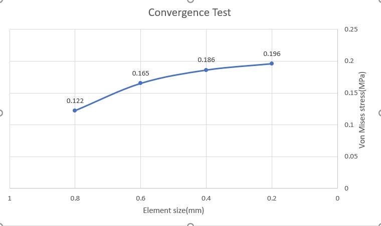
Do a convergence test on the quantity you care about. For you, that is force.
To simulate a contact that can separate, the only choice is Transient Structural without connecting any Modal solution into the Setup cell. A Transient analysis requires you to use a force vs time input. That means you have to type the equation using A*sin(f*time) into the Force details. A is the value you were using in Harmonic Response while the constant f defines the frequency of oscillation. There is a place to type Segments, which must create 20 points per cycle. If you want to simulate 1 second of 30 Hz, then you need Segments to be 20*30*1 = 600. To simulate 1 second, under Analysis Settings, the Minimum Substeps must be 600 also.
A Transient Structural model with that many nodes will take tens of hours to run and require maybe a TB of disk storage unless you turn off Strain and maybe Stress in the output controls. I don't recommend you go to Transient Structural.
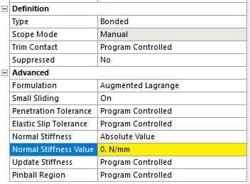
The device has a soft silicone rubber (low Young's Modulus) covering a hard plastic plate (high Young's Modulus), but you haven't modeled that composite structure. I recommend changing all the frictionless contacts to Bonded Contact. You can change all of them at once by selecting them all. The details window will change all of them. In addition, change the Normal Stiffness Value. That way, the tooth will have the correct low stiffness connection to the plate.
Once the teeth are all bonded to the plate, you can delete the bogus displacement boundary condition on the four edges of the plate at the far end. Those are not real.
-
April 7, 2020 at 11:44 am
Amin1372
SubscriberHi Peter Thank you so much for helfpul recommendation.
Yes I will go through Harmonic Analysis because that is less time taking.
But if I change the connections to bonded, tensile forces will appear again in the results which is far away from reality.
And for Harmonic Analysis I still need to use about 200 modes which needs a super computer to converge them.
My question is that can I do the analysis with half of the geometry as it is fully symmetric? At least I can reduce the number of nodes and elements.
And did you mean that Normal Stiffness Value should be zero? What will be its effect or advantages? -
April 7, 2020 at 9:43 pm
peteroznewman
SubscriberThe bonded contact with a low normal stiffness will not generate high forces because as the plate moves, the force is spread over many teeth.
Don't make it a symmetric model because some of the vibration modes are not symmetric.
Since you are not interested in Stress, but Force, you can greatly reduce the number of nodes in the model. With a reduced number of nodes, the Modal analysis of 200 modes can be done on your laptop.
You have to figure out the spring rate of the tooth pressing into the silicone rubber. You could do a single tooth pressing into a block of rubber in Static Structural to calculate the spring rate if you use the proper Young's Modulus for silicone rubber.
Â
-
April 15, 2020 at 9:24 pm
Amin1372
SubscriberHi Peter,
I found a powerful computer working with 80 cores in parallel but the simulation time of my project still be like my laptop which is weird. How Can I use the maximum potential of the system?
-
- The topic ‘Mesh convergence’ is closed to new replies.
-
4042
-
1461
-
1308
-
1151
-
1021
© 2025 Copyright ANSYS, Inc. All rights reserved.