-
-
March 7, 2020 at 12:53 am
Amin1372
SubscriberHello,
I am doing transient analysis which I want to apply 0.3 N sinusoidal force with frequency of 30 Hz on a part.
But I don't know how to set the step setting like step end time, and also don't understand the difference between defining them by time or substeps.
After applying this force I need to just get the maximum reaction force of the other parts affected by that force so my question is that how many cycles or seconds should I run and is it true to run that for just one cycle?
Â
Thanks,
Â
-
March 7, 2020 at 1:28 am
peteroznewman
SubscriberDon't use a Transient Structural analysis to get these answers.
Use a Modal analysis and a Harmonic Response analysis linked together. Drag the Solution cell from the Modal analysis onto the Setup cell of the Harmonic Response.
In the Analysis Settings of the Modal analysis, request enough modes until you have modes that are up to 60 Hz. There are more detailed rules but this will get you started.
In the Analysis Settings of the Harmonic Response, request results in the frequency range of 25 to 35 Hz.
Apply a load of 0.3 N. It will be treated as a sinusoidal force and the frequency will be swept over the range specified above. You can plot the maximum reaction force as a function of frequency.
-
March 7, 2020 at 1:33 am
Amin1372
SubscriberThanks Peter for your help but my model is nonlinear. Can I use harmonic analysis? -
March 7, 2020 at 1:53 am
peteroznewman
SubscriberNo, Harmonic is a linear analysis, but you should run that before you spend time on a Transient Structural to get an estimate.
You should also get Modal results before you run a Transient so you know the frequency of the modes around the 30 Hz forcing frequency.
The rule for Transient Structural time steps is that the maximum time step should put 20 steps in the 30 Hz cycle. That means 600 steps/second or a time step of 0.00167 seconds.
You must add some Damping to the model. Is there a physical prototype to obtain some vibration data from?
-
March 7, 2020 at 11:42 am
Amin1372
SubscriberYes this is a device used in orthodontic treatment which applies vibrational force on the teeth to stimulate them to increase their cell activities.
I will do that for harmonic first to get some approximate results but I still have few questions that I really appreciate if you can help me:
1. Is it necessary to get Modal results? can I go straight forward to the harmonic analysis?if SO, how many modes will I need?
Â
2. When I define the steps and step time I get this error. Honestly I don't understand how these options work? also when the auto time stepping and time integration should be on?
Â
Â
3. I don't know what is the damping coefficient of my model, can I assume a small number?Â
Thank you so much.
-
March 7, 2020 at 5:36 pm
peteroznewman
Subscriber1. A Modal analysis solution linked into the Setup cell of the Harmonic Response will reduce the solution wait time because it will only be solving the motion of the modes you included in the Modal, and not use all the individual nodes in the mesh. But you must include a sufficient number of modes.
2. In a Transient Structural model, use Number of Steps = 1 and an End Time of 1 second. Then you will get 30 cycles from your load. The time step of 1.67e-3 s will make sure you have 600 solutions over the 1 second, which is adequate to get a smooth response from a 30 Hz forcing frequency.
-
March 8, 2020 at 9:43 pm
Amin1372
SubscriberDear Peter,
I did Modal analysis and got 10 natural frequencies, starting from 308 Hz to 19209 Hz. But I want do harmonic analysis for 30 Hz sinusoidal force. How true is it to connect the modal results to harmonic setup as the natural frequencies are very different from what I want to use?Â
Â
Thanks
-
March 9, 2020 at 2:35 am
peteroznewman
SubscriberYou will get basically a static response from the structure when you apply a 30 Hz forcing frequency to a structure with a 308 Hz first natural frequency. By static response, I mean the structure will almost perfectly follow the input force. When the force is at its positive peak, the structure will have the same deformation as if you applied that positive force statically, and when the force is at its negative peak, the structure will have the same deformation as if you applied that negative force statically. If the force amplitude is high, then the deformation will be high, if the force amplitude is low, the deformation will be low.
-
March 9, 2020 at 12:50 pm
Amin1372
SubscriberDear Peter,
So you mean these natural frequencies even if they are very high, don't matter. Am I right? sorry for these fundamental questions.Â
And how many natural frequencies do I need to make sure my results will be accurate?
And last thing, how about damping, is that necessary to define it? there is a damping option in solver control to set it on, is that enough to solve the model with this option?
Thanks
-
March 9, 2020 at 11:01 pm
Amin1372
SubscriberHi Peter,Â
I faced some question again. My simulation is done which was modal+harmonic and then I got some reaction forces but there are two ways to get them:
(probe and then force reaction) or (frequency response and then force reaction). which one gives me the force reaction of the sinusoidal force of 30Hz?
Â
Best,
Â
-
March 10, 2020 at 12:36 pm
peteroznewman
Subscriber
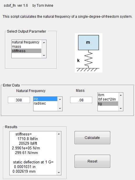
A Single Degree of Freedom (SDOF) system has a mass connected to ground through a spring. The spring-mass system has a natural frequency. If you study dynamics, you will find there is a standard equation to predict the motion of that SDOF system to sinusoidal input. You gave me all the inputs I needed except for the mass, so I used 80 grams. If you have a sinusoidal force of 0.3 N acting on that mass, and the natural frequency is 308 Hz, the reaction force on the ground is going to be 0.303 N and the displacement is going to be 1 micron. I used matlab and a script written by Tom Irvine to solve the standard equations.
Here is the spring stiffness needed to get 308 Hz with an 80 gram mass:
At these low forcing frequencies, I don't think there will be much difference how many modes you include, but the cost of including them is low so put in 6.
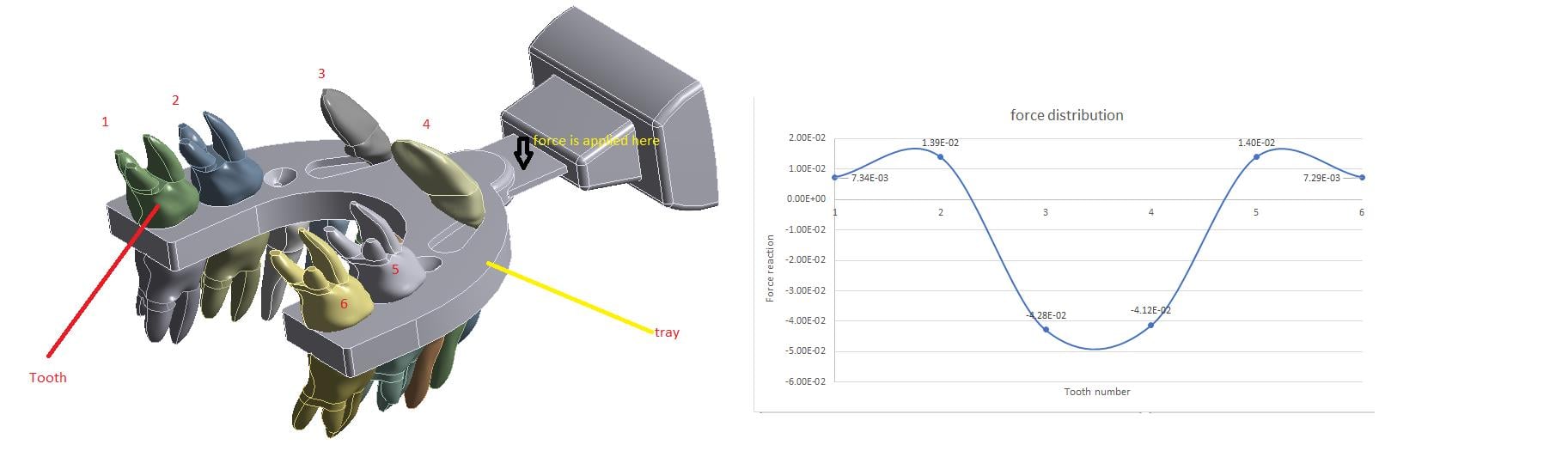
I expect either way of obtaining the Reaction Force will work. If you do it both ways, do you get the same result?
Â
-
March 10, 2020 at 1:09 pm
Amin1372
SubscriberHi Peter,Â
Thanks you so much for your help.
I got confused because I didn't understand what the purpose of having stiffness is. I would appreciate if you take a look at my model attached here and see if the those modal analysis are true. I'm really grateful if you do this favor for me.
Yes both ways give me the same results.
Also if you look at the plot of force reaction for six parts( which are human teeth), you will see some are positive and the rest are negative which I expect only tensile ones not compression because the connection between teeth and tray are not bonded. What would be the reason?
Best,
Amin
-
March 13, 2020 at 2:51 pm
Amin1372
Subscriber -
March 13, 2020 at 5:05 pm
peteroznewman
SubscriberThe material specified for the bite plate in your model is crystalline silicon, which is almost as hard as steel. I would have thought a bite plate would have been made of a hard plastic like Acrylic, or maybe a soft material like ethylene vinyl acetate (EVA), which is used for Night Bite Guards to protect teeth from grinding.
For reference, here are the Young's Modulus values of the stiffness of each material including the two in your model.
- Steel  = 200 GPa
- Silicon = 166 GPa this is what you are using for the bite plate
- Tooth  = 20 GPa this is what you are using for the teeth
- Acrylic =Â Â 2.7 GPa
- EVAÂ Â <Â Â 0.1 GPa
Please reply with what you intended to use for the bite plate.
-
March 13, 2020 at 5:34 pm
Amin1372
SubscriberPeter,
Actually this device is used for stimulating teeth by applying vibrational force to increase the functionality of the their cells which can speed up the process of tooth movement during the orthodontic treatment. we just know the material is silicon covered by plastic but I myself have doubt about the elasticity of that kind of silicon we used in the Ansys because it's very stiff and more like Steel. Please help in this case because I am very novice about material properties.
Thanks in advance,
Amin
Â
-
March 13, 2020 at 7:10 pm
peteroznewman
SubscriberAmin, a silicon crystal slice feels like a plate of steel. This device uses something like a blue Acrylic plastic bite plate coated in a clear elastomer like EVA or silicone rubber. Check your source and you will find that it is silicone not silicon and the letter e on the end makes the stiffness be reduced by about a factor of 1000.
Â
You can't build any models if you don't know the mechanical properties of the materials. Reply when you have confirmed the materials used. When you have the two materials: the blue plate inside and the clear material molded over that, then you need geometry that has both materials. You can't use the geometry with just one material.
-
March 13, 2020 at 8:35 pm
Amin1372
SubscriberHi Peter,
Yes I will correct the material and geometry because as you said they are not realistic but does the coating layer have significant effect on the results?
And just a question from my last post, if you look at the plot of the force reaction for six parts( which are human teeth), you will see some are positive and the rest are negative which I expect only tensile ones not compression because the connection between teeth and tray are not bonded, they are frictionless. What would be the reason?
Â
Â
Â
Â
Thanks,
Amin
-
March 13, 2020 at 10:03 pm
peteroznewman
SubscriberYes the coating has a significant effect because is may be about 100 times softer than the plate. It is also likely to be a hyperelastic material, which means it is nearly incompressible, which means when the tooth applies pressure, the material has a nearly constant volume as it deforms.
The first model bears no resemblance to the real device. Discard the results from that model and focus on building a more representative model.
The roots of the teeth are not fixed, they flex relative to the bone. You will need to get the material properties for the periodontal ligament around the tooth as I expect that has much lower stiffness than the tooth or bone and acts like a spring, allowing the tooth to move.
-
March 21, 2020 at 8:06 pm
Amin1372
SubscriberHi Peter,
I changed the material from Silicon to Silicone rubber for the blue plate but we just need this part and we ignored the coating layer to simplify the model. My problem now is that when I input the Young's modulus( Average value: 0.0793 GPa) and Poisson ratio (Average value: 0.500) for Silicone rubber in Ansys, the Bulk modulus goes to infinity!!!!! Am I wrong?
Thanks
Amin
-
March 22, 2020 at 1:53 am
peteroznewman
SubscriberA Poisson's Ratio of 0.5 defines an incompressible material, which by definition has a Bulk Modulus of infinity.
That is why there are Hyperelastic materials. These use a different material model that can be incompressible.
Look in Engineering Data and you can find some Hyperelastic materials.
-
March 22, 2020 at 10:15 am
Amin1372
SubscriberHi,
But Ansys has no complete library for Hyperelastic materials. I see Silicone rubber in Engineering data but it doesn't have Young's modulus or Poisson ratio, can I use that? I mean does it have correct material properties?
Â
Thanks,
Amin
-
March 22, 2020 at 11:06 am
peteroznewman
SubscriberANSYS provides a selection of material models, you need to provide your own data for your specific material. ANSYS provides curve fitting software to compute the constants needed for different choices of material model from experimental data. There are standard lab tests to generate the experimental data like Uniaxial Tension, Biaxial Tension, Uniaxial Compression etc.
-
March 22, 2020 at 11:40 am
Amin1372
SubscriberSo providing my own data and getting the curve of young's modulus would be enough? what if the curve is not linear? do I need to do Transient instead of Harmonic analysis?
-
March 22, 2020 at 3:01 pm
peteroznewman
SubscriberHarmonic Response is a linear analysis so you can only use linear material. You will have to use Linear Elastic material properties. Estimate the Young's Modulus for the start of the nonlinear stress-strain curve. You can set Poisson's Ratio to 0.495 to represent a nearly incompressible material.
-
March 23, 2020 at 5:07 pm
Amin1372
SubscriberHi Peter,
You mean instead of using curve fit I can use the Young's modulus with poisson ratio of 0.495?
Â
Â
-
March 23, 2020 at 8:45 pm
peteroznewman
SubscriberYes, exactly.
-
March 25, 2020 at 10:56 am
Amin1372
SubscriberThanks Peter, I changed the material properties like what you said.
I need your help for Modal Analysis because some deformations are very large( in true scale mode) and I think these might be because of the boundary conditions I defined. Could you please take a look at my B.C's and modal shapes?
Thanks in advance -
March 25, 2020 at 11:33 am
-
- The topic ‘Transient Analysis’ is closed to new replies.
- The legend values are not changing.
- LPBF Simulation of dissimilar materials in ANSYS mechanical (Thermal Transient)
- Convergence error in modal analysis
- APDL, memory, solid
- How to model a bimodular material in Mechanical
- Meaning of the error
- Simulate a fan on the end of shaft
- Nonlinear load cases combinations
- Real Life Example of a non-symmetric eigenvalue problem
- How can the results of Pressures and Motions for all elements be obtained?
-
3882
-
1414
-
1241
-
1118
-
1015
© 2025 Copyright ANSYS, Inc. All rights reserved.