
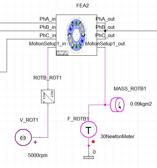
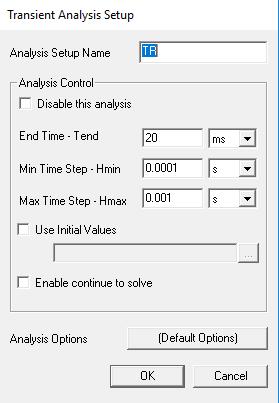
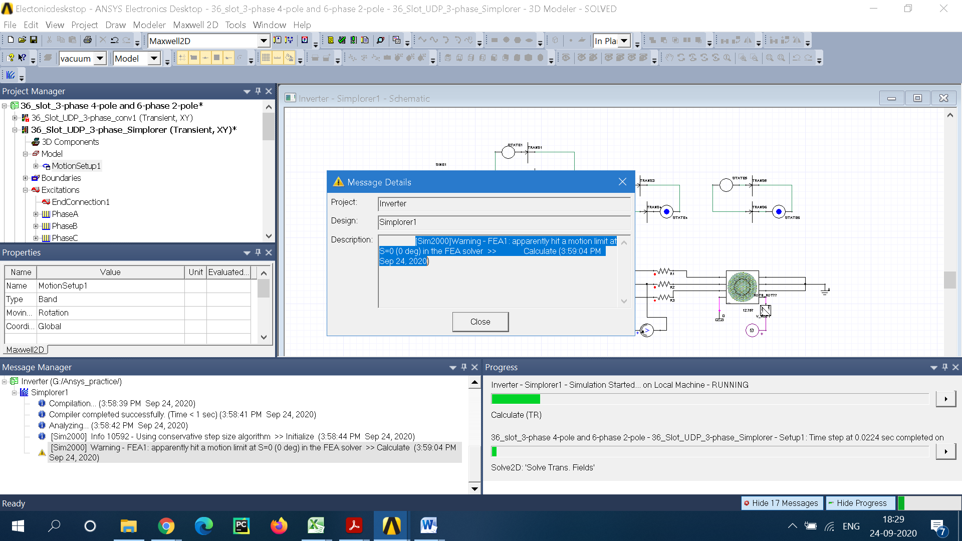
Motion setup terminals in Ansys Maxwell-Simplorer/cosimulation


Viewing 17 reply threads
- The topic ‘Motion setup terminals in Ansys Maxwell-Simplorer/cosimulation’ is closed to new replies.


