TAGGED: #fluent-#cfd-#ansys
-
-
January 9, 2025 at 3:33 pm
l.hutcheson1
SubscriberI’m trying to simulate a hybrid Darrieus VAWT and I’m coming across a unusual issue:
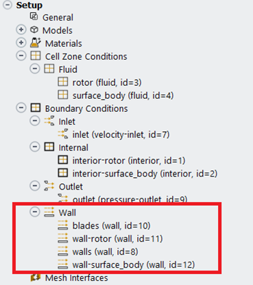
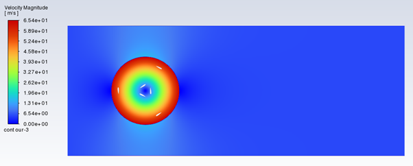
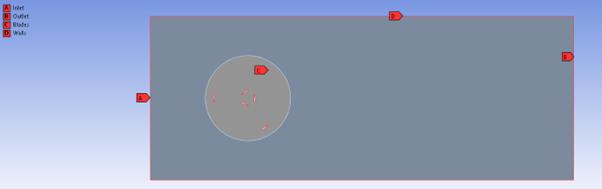
It seems that the edge of the rotor area is being defined as the inlet instead of the inlet itself (Image 1), despite the simulation being set up identically to another working simulation with slightly different dimensions. My suspicion is that this stems from the creation of new contact regions under boundary conditions which are present in this model (Image 2), but not the other working model. These also appear under “Mesh Interfaces” leading me to believe this is what is stopping the mesh from sliding. In the working model, it is only “blades” and the lines which make up the wall region each being named “wall XX” (Image 3) that are under the Wall heading here, otherwise all setup parameters are the same between models.
The issue also seems entirely related to the angular rotation of the rotor, since varying the inlet velocity has no effect on the simulation. I've tried to create the entire system again, but it leads to the same result. the simulation is in 2D and large structure support is enabled.
Thanks for your help.
-
January 9, 2025 at 3:57 pm
Rob
Forum ModeratorThe surface (interface) pair between the two zones needs setting up. It looks like you currently have a pair of walls.
-
January 12, 2025 at 1:31 pm
l.hutcheson1
SubscriberAny idea on how I should set this up?
-
-
January 13, 2025 at 11:02 am
Rob
Forum ModeratorYes, have a look at the interface functions in Fluent's User Guide. They're covered in Boundary Conditions.
-
January 21, 2025 at 4:36 pm
l.hutcheson1
SubscriberHi Rob,
Thanks for your help so far, I've managed to run the simulations and the contours look as expected, however, the output torque is much less than expected by a factor of nearly 10^4. Any ideas on what could be causing this?
-
-
January 21, 2025 at 4:44 pm
Rob
Forum ModeratorCheck the domain scale? I assume you've set the centre point? Also, are you moving the VAWT using moving mesh at a fixed speed or based on the force/flow speed?
-
January 23, 2025 at 11:20 am
l.hutcheson1
SubscriberI've double checked the domain scale and moment co-ordinates and they're correct. The movement is based on inlet velocity in boundary conditions and a rotational velcoity for the rotor in cell zones conditions.
-
-
- You must be logged in to reply to this topic.
- How do I get my hands on Ansys Rocky DEM
- Non-Intersected faces found for matching interface periodic-walls
- Unburnt Hydrocarbons contour in ANSYS FORTE for sector mesh
- Help: About the expression of turbulent viscosity in Realizable k-e model
- Script Error
- Mass Conservation Issue in Methane Pyrolysis Shock Tube Simulation
- Facing trouble regarding setting up boundary conditions for SOEC Modeling
- convergence issue for transonic flow
- Running ANSYS Fluent on a HPC Cluster
- Point exception in erosion calculation
-
1882
-
802
-
599
-
591
-
366
© 2025 Copyright ANSYS, Inc. All rights reserved.