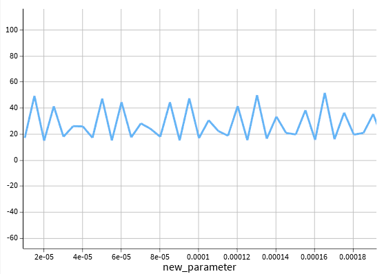
Following Amrita's instructions for conducting a convergence test, I swept the mode loss versus the simulation region.
However, the result was the following graph:
- The core width is approximately 2.5 µm, and the thickness is 350 nm.
- I spanned FDE region from 10um to 200um.
Should I use other methods to extract accurate loss data, such as FDTD with a monitor in the ZX direction or FEEM? (or changing PML settings)
- I’m also curious about the accuracy of the PML settings for this type of structure. Is it appropriate for simulations involving infinitely extended structures?
Thank you for your support.
==============================================================================
(12/9 https://innovationspace.ansys.com/forum/forums/topic/fde-simulation-region-and-loss-change-in-mode/)
Hello, I am studying hybridized modes between slab and buried waveguides.
During the process of setting the FDE simulation region, I noticed that the loss changes drastically depending on the simulation region, even when all other conditions remain the same.
Since most of the loss is caused by slab modes (due to coupling with slab modes), I believe this phenomenon is plausible.
However, at the same time, I suspect it may be an inaccurate result.
Do you have any suggestions on how to resolve this issue?
I would really appreciate it if you could help me.
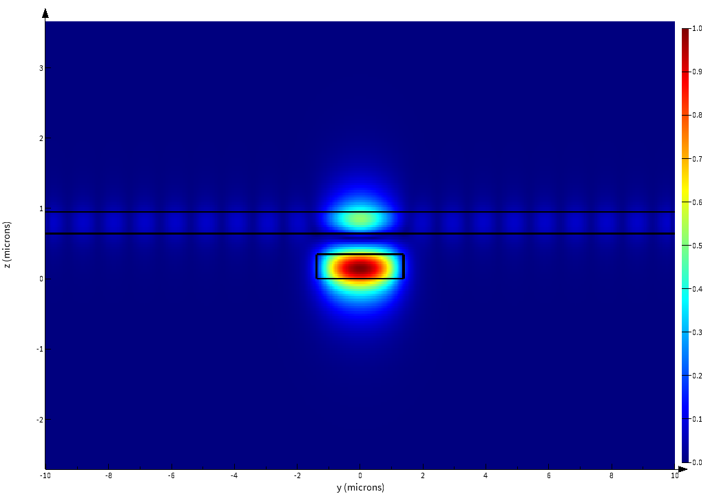
- I set my simulation region with PML boundaries (default condition). (for hybridized mode with upper slab and lower buried waveguide)
- If I span simulation region(along y axis) to 5*core width, 6*core width, 7*core width -> I found that the loss changes to 6.3051dB/cm, 4.36dB/cm, 31.9dB/cm.
==============================================================================================================


