TAGGED: face-meshing, fluid
-
-
December 12, 2024 at 3:52 amanishkommireddySubscriber
Hello,Â
So I have a problem with my face meshing. I don't understant what is happening.Â
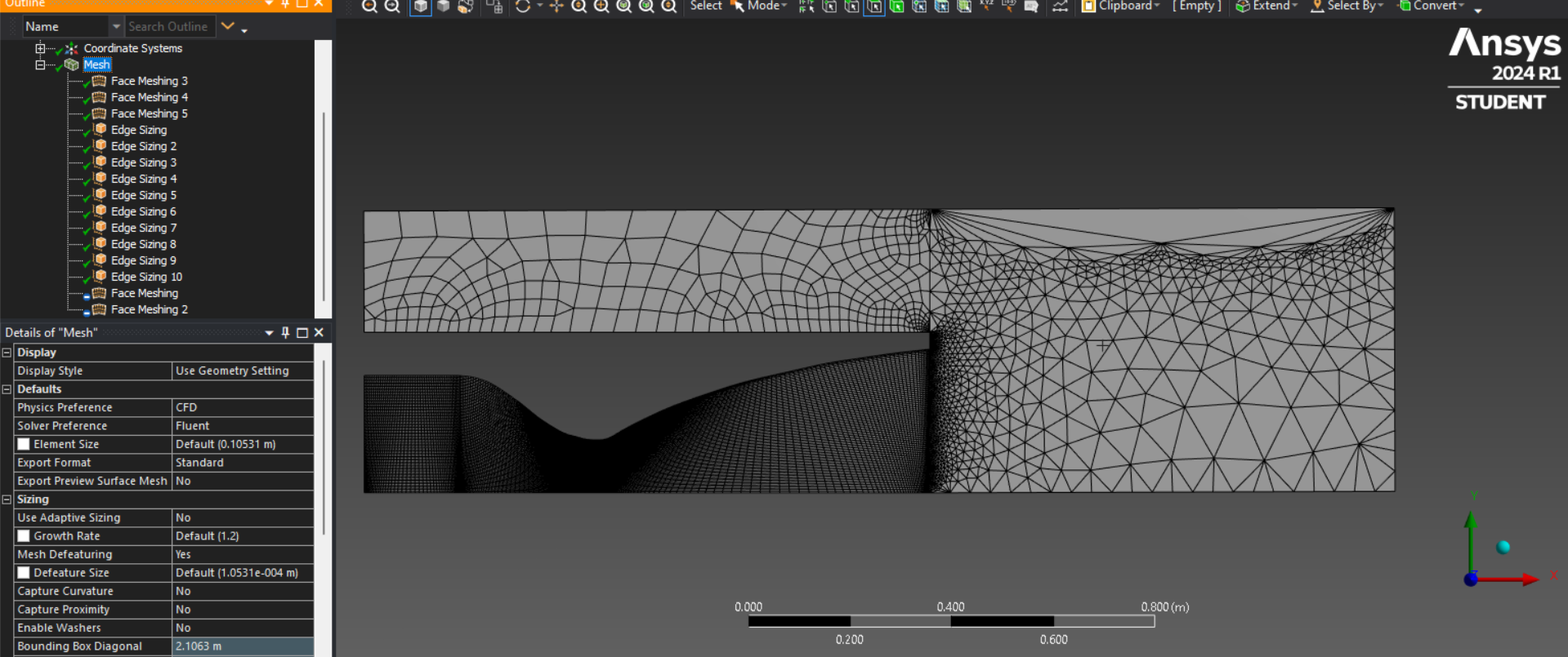
One notable thing that may be important for whatever is happening is that there is a blue minus sign next to the face meshings for the two problematic face meshes in the tree.
Also, whenever I try to use face sizing then element sizing, it somewhat fixes, but then just introduces random irregularities throughout the mesh. And when I use the element sizing, it ignores any edge sizing I do to the tiny little edge right above the end of the nozzle. By that I mean that the mesh doesn't get more dense and kind of just converges the extra divisions into points and ignores it.
Is there a problem in the face mesh that is indicated by the blue minus sign, and is there a way to fix it? Or is the problem elsewhere? Also I don't know how to add a file onto this.
-
December 12, 2024 at 9:49 amDeepakAnsys Employee
Â
Hi,
The blue status icon that may appear in the Tree Outline indicates that a mapped mesh cannot be provided on the scoped topology. This icon is triggered under one of three scenarios: the face cannot be map meshed, the quality of the mapped mesh was not acceptable and a free mesh was generated, or if the ‘Constrain Boundary’ is set to ‘Yes’ [Notes on Face Meshing Controls for Mapped Meshing]
To address the issue, you might want to check if the geometry looks problematic, especially if there are very sharp or thin faces, or if the graphics appear corrupted. You can try several options to resolve meshing problems: Troubleshooting
1. Add local size controls to reduce mesh size or modify defeaturing tolerance.
2. Merge faces locally using Virtual Topology.
3. Add a local Pinch control.
4. Modify the geometry in the problematic location using a geometry tool.
5. If the edges attached to the problematic face may be causing issues, inspect them for problems.See this post,
Search the video title with "Ansys tutorial 2D Meshing: Nozzle" on YouTube.
2D Transient Diffusion Geometry and Meshing | Ansys Courses
2D Beam Planar Approx. Mesh | Ansys Innovation Courses
Basic Meshing for Structural Simulation Using Ansys Mechanical | Ansys Knowledge
Thanks,
Deepak
Â
-
December 12, 2024 at 9:55 amabhishek.royAnsys Employee
Â
Also, the mesh downstream the nozzle exit should be finer to capture shocks or expansion waves depending on overexpanded or underexpanded flowÂ
Â
-
December 14, 2024 at 6:58 amanishkommireddySubscriber
I am trying to follow this tutorial: ANSYS Fluent: Rocket Engine Nozzle (With Exhaust Plume) - Detailed & Accurate CFD Tutorial.
In the tutorial, they use that kind of geometry, but their meshing actually works first try. I am cutting up the faces of my geometry exactly how they do it, and the only difference is that I am using the different meshing tool than they use. However, I still don't understand why mine does not work at all while their's does. Also the problem only occurs on that area right outside of the edge of the nozzle, the corner.Â
-
January 6, 2025 at 11:35 amabhishek.royAnsys Employee
In the video you have shared they are using a structured mesh. But in your case, you are using a hybrid mesh and the region outside the nozzle has unstructured mesh. The issue could be the incorrect growth rate and edge sizing.Â
-
- You must be logged in to reply to this topic.
- CONVERTING STL FILE IN TO SOLID
- Varying ply angle in ACP
- The meshing algorithm cannot find matching topology
- Assiging one parameter as thinkness of few shell objects
- [ANSYS Meshing] how to activate curvature for a sizing in a script?
- How to create a mapped mesh in a chain link model with stud.
- ICEM O grid mesh for sloped pipe
- How do I fix this irregular face meshing problem?
-
1882
-
802
-
599
-
591
-
366
© 2025 Copyright ANSYS, Inc. All rights reserved.