Photonics

Photonics

Topics related to Lumerical and more.

Lumopt: Unable to calculate gradient after changing dielectric constant

    • fachienchong
      Subscriber

      Hello,

      I encountered the following issues while using lumopt for inverse design.
      In the official case, the given dielectric constant is 1.44/2.80, corresponding to the background and device, respectively. I changed it to 1/3.48 in order to simulate the actual situation, which caused the program to not run.
      The specific situation is as follows,
      Run according to the dielectric constant provided in the case, perform forward and adjoint simulations, and calculate the gradient to enter the first iteration.


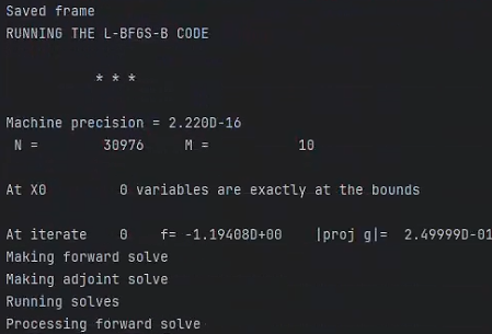
      After changing to silicon and air, the gradient cannot be calculated after forward and adjoint simulation, and it remains here.


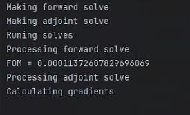
      In addition, when the mesh accuracy is adjusted from 2 to 3, similar situations may occur where gradients cannot be calculated.
      If there is a solution, I would be very grateful.

      best regards

      fachien

    • fachienchong
      Subscriber

      Addendum: Based on the suggestions in the previous post, I tried to make modifications in the original official case, and in fact, it worked normally. But I noticed that the official case is a 2D simulation, while my modeling is a 3D simulation. Is this the reason for the problem?

    • fachienchong
      Subscriber

      In addition, I also found that only changes in the dielectric constant of the waveguide have an impact on the program, while changes in the dielectric constant of the design area have no effect.

    • anna.wirth-singh
      Ansys Employee

      Hi Fachien,

      Thank you for providing information about your case. Could you please clarify, is this a topology optimization or a shape outline optimization? 

      If you are not already doing so, please try adding a mesh override region over the optimizable geometry. Lumerical uses an adaptive mesh, so in inverse design the mesh will update as the geometry is changed. This can sometimes cause issues calculating the gradients in lumopt. So the solution is to use a mesh override region over the optimizable geometry to ensure that the mesh grid remains fixed during optimization. 

      Also, I have one follow-up question. After you change the dielectric constants, does the starting simulation produce the expected results? It would be good to double check that there is no issue with the initial simulation. 

      Best,

      Anna

    • fachienchong
      Subscriber

      Hi Anna,
      Thank you for your reply.
      I am currently working on topology optimization.
      I added mesh to my design area and fom area, with a step size of one tenth of the center wavelength. In fact, this is indeed useful, although it greatly increases my simulation time.
      According to the current settings, the refractive index comparison can be increased to 1/3.40, although there is still a distance from the actual refractive index, it can also be used as an approximate solution. My goal is to have a refractive index of 1/3.48
      If I want to obtain a more accurate solution, should I increase the mesh or how to adjust the settings.
      Additionally, I have noticed that making the above adjustments may result in the broadband simulation not being effective.
      Look forward to your reply.
      best
      fachien

    • anna.wirth-singh
      Ansys Employee

      Hi Fachien,

      Thank you for the response; I'm glad the mesh override helped. To clarify, the most important part of the mesh override is not really to make the mesh finer (one tenth of a wavelength is probably higher resolution than necessary in most cases) but instead it is to force the simulation to use a consistent mesh grid in each simulation. 

      That being said, your note that the simulation is successful as 1/3.4 but not 1/3.48 makes me think that the issue is still related to meshing. The reason is, for a high refractive index material (n = 3.48 is quite high), the wavelength of light is much shorter in that material than in the air. So if your wavelength is lambda in air, then it is lambda/n in the medium. Sampling the mesh at lambda/10 is very accurate for the air, but the sampling is effectively much less in the silicon because of the higher refractive index. 

      I will get back to you about potential solutions to this problem. The benefit of adaptive meshing is that it automatically samples according to the refractive index to maintain the desired accruacy, but changing the mesh causes issues with lumopt. On the other hand, sampling the entire area at a very fine mesh greatly increases computation time. At the moment, I think that increasing the mesh sampling is the most likely solution.

Viewing 5 reply threads
  • You must be logged in to reply to this topic.